
Ni/Fe Bimetallic Ions Co-Doped Manganese Dioxide Cathode Materials for Aqueous Zinc-Ion Batteries


State Key Laboratory of Advanced Technology for Materials Synthesis and Processing, Wuhan University of Technology, Wuhan 430070, China
*
Author to whom correspondence should be addressed.
†
These authors contributed equally to this work.
Batteries 2023, 9(1), 50; https://doi.org/10.3390/batteries9010050
Submission received: 9 December 2022
/
Revised: 3 January 2023
/
Accepted: 9 January 2023
/
Published: 11 January 2023
(This article belongs to the Collection Advances in Battery Materials)
Abstract
:The slow diffusion dynamics hinder aqueous MnO2/Zn batteries’ further development. Here, a Ni/Fe bimetallic co-doped MnO2 (NFMO) cathode material was studied by density functional theory (DFT) calculation and experimental characterization techniques, such as cyclic voltammetry (CV), galvanostatic intermittent titration technique (GITT) and electrochemical impedance spectra (EIS). The results indicated that the energy band structure and electronic state of MnO2 were effectively optimized due to the simultaneous incorporation of strongly electronegative Ni and Fe ions. Consequently, the NFMO cathode material exhibited a faster charge transfer and ion diffusion dynamics than MnO2 (MO), thus, the assembled NFMO/Zn batteries delivered excellent rate performance (181 mA h g−1 at 3 A g−1). The bimetallic ions co-doping strategy provides new directions for the development of oxide cathode materials towards high-performance aqueous zinc-ion batteries.
1. Introduction
Compared with flammable and toxic organic electrolytes, the aqueous electrolyte of a water system battery has inherent advantages of high safety, low cost, and environmental friendliness, which makes its deployment in the field of large-scale energy storage have great potential [1,2,3,4]. In particular, aqueous zinc ion batteries (AZIBs) have induced the greatest attention for the rich resources, high theoretical specific capacity (820 mA h g−1) and low reduction potential (−0.76 V vs. standard hydrogen electrode) of zinc metal as negative pole [5,6,7,8]. Hitherto, various cathode materials, including Mn-based compounds, V-based composites, Prussian blue analogs, and organic compounds, have been widely reported in AZIBs [9,10,11,12,13]. Among all of these materials, Mn-based cathode materials, such as MnO2, are generally considered to be more promising due to their high theoretical specific capacity, low price, and suitable voltage [14,15].
Nevertheless, the further development of MnO2 cathode material is restricted due to its poor electronic conductivity, blocked ionic diffusion, unstable structure, and complex reaction mechanism [16]. Strenuous efforts have been made to improve the electrochemical performance of MnO2 by ion-doping [17], pre-intercalation strategy [18], and compositing with heterogeneous conductive materials [19]. Among them, the ion-doping method has been favored by a multitude of researchers because it can induce some defects in the crystal structure, thus improving the ionic conductivity, electronic conductivity and reactivity [20]. Lv et al. proposed a copper-doped δ-MnO2 nanosphere cathode material with rich manganese/oxygen defects, which exhibited excellent cycle stability (capacity retention rate exceeded 70% after 1000 cycles) due to the manganese defects triggering the lattice oxygen redox reaction mechanism [21]. Pu et al. successfully realized Ag-doped δ-MnO2, and its effective performance promotion is attributed to the improvement of diffusion kinetics, which is due to the formation of Ag–O–Mn bonds, which result in a large number of oxygen vacancy defects [22]. However, most reported materials are doped with single metal ion, showing relatively limited modification effects for the little defects [23]. At the same time, the selection of suitable elements for bimetallic doping is a problem. Bimetallic ion-doping technology can induce abundant defects and more significantly regulate the electronic structure of material, further enhancing the reaction kinetics and reactivity of material [24,25]. Therefore, MnO2 bimetallic ion-doping technology will be an important method for the further development of high-performance AZIBs cathode materials.
Herein, the material modification mechanism of bimetallic ion-doping was studied based on DFT calculation and an NFMO cathode material was developed through a simple hydrothermal process. The electronic conductivity, ionic conductivity, and reaction activity of the NFMO cathode material are significantly improved compared to those of MnO2 due to the large number of vacancy defects produced by bimetallic ion-doping. As a proof of concept, the NFMO cathode material delivered high capacity output (382 mA h g−1 at 0.1 A g−1) and superior rate performance (181 mA h g−1 at 3 A g−1).
2. Materials and Methods
2.1. Synthesis of NFMO and MO
Acetylene black and concentrated nitric acid were first mixed homogeneously. The mixture was transferred to a 100 mL Teflon autoclave and sealed in an oven at 60 °C for 12 h. After being cooled to room temperature, it was washed to neutral with deionized water and absolute ethanol, and then dried in a vacuum oven at 60 °C for 12 h. A total of 60 mg treated acetylene black, 0.79 g KMnO4, 0.29 g Ni(NO3)2 and 0.404 g Fe(NO3)3 were dissolved in 50 mL of deionized water. Subsequently, 1 mL of H2SO4 (10 vol%) solution was added into the resulting solution and stirred for 30 min. The mixed solution was kept in a water bath at 120 °C for 12 h. The resultant NFMO was collected by centrifugation, washed thoroughly with deionized water and dried at 80 °C. MnO2 without co-doping was synthesized by removing Ni(NO3)2 and Fe(NO3)3 above. NMO and FMO are obtained by adding the same amount of dopant.
2.2. Electrochemical Measurements
For electrochemical evaluation, the batteries were assembled using the MnO2 electrode as the cathode, glass fiber as the separator and Zn foil as the anode in coin cells (CR2016). The working cathode was composed of mixing active materials (70 wt%), acetylene black (20 wt%) and polyvinylidene fluoride (PVDF) (10 wt%) in N-methyl pyrrolidone (NMP) solvent. The slurry was then pasted on a graphite paper followed by drying at 70 °C overnight. After that the carbon paper was cut into round sheets with a diameter of 10 mm as cathode. The aqueous electrolyte was 3 M ZnSO4 + 0.2 M MnSO4. Galvanostatic charge/discharge curves were performed on a Neware battery tester (BTS-4000, purchased from NEWARE TECHNOLOGY LIMITED of Shenzhen, China) at different current densities and in a cut-off voltage range of 0.9–1.8 V. CV and EIS were measured on EC-LAB electrochemical workstation in the voltage and frequency ranges of 0.9–1.8 V and 0.01 to 100 kHz, respectively.
2.3. Materials Characterizations
Scanning electron microscopic (SEM) images were collected using a JEOL-7100F scanning electron S-5 microscope at 20 kV. Transmission electron microscopic (TEM) and high-resolution TEM (HRTEM) images were performed on a JEM-2100F. The elemental distributions were obtained from energy dispersive spectroscopy (EDS) mapping analysis. X-ray diffraction (XRD) data of the samples were collected using a Bruker D8 Discover X-ray diffractometer equipped with a Cu Kα radiation source. X-ray photoelectron spectroscopy (XPS) were carried out using an ESCALAB 250Xi instrument. Raman spectra were recorded by a Renishaw INVIA micro-Raman spectroscopy system. The carbon contents were obtained from thermos-gravimetric (TG) (NETZSCH STA 449F5) measurements during which the samples were heated to 800 °C in air with a heating rate of 10 °C min−1. The Inductively Coupled Plasma Optical Emission Spectrum (ICP) was carried out by a PerkinElmer Optima 4300DV spectrometer. Raman spectra were recorded by the Renishaw INVIA micro-Raman spectroscopy system.
2.4. First-Principles Calculations
The first-principles calculations were carried out by using Vienna Ab-initio Simulation Package 5.4.4 software with DFT and projector augmented-wave plane-wave pseudopotential method. The generalized gradient approximation with the Perdew–Burke–Ernzerhof function was applied to describe the electron exchange-correlation functions. The four crystal surface models, based on shearing the primitive cell of MnO2 along the (001) crystal plane, had a vacuum thickness of 15 Å in the z-direction to avoid interaction between the slabs. The kinetic energy cutoff of electron wave functions was used as 400 eV. The K-point meshes used for the first Brillouin zone integration were generated by Gamma-center as 1 × 1 × 1 for optimization, due to large size supercell, and 2 × 2 × 1 for electric properties calculation. The energy band structure of each system was calculated by the closed K-point grid path of G-F-Q-Z-G. An energy convergence of 10−4 eV/atom and force convergence of 0.03 eV/Å are ensured for all geometry relaxations. In addition, for all the calculations, spin polarization was considered. Visualization of electronic and structural analysis software was used to draw the crystal structure diagrams.
3. Results and Discussion
We have designed a method of synthesizing bimetallic-doped layered MnO2 nanoflowers with oxygen defects by a one-step hydrothermal method shown in Figure 1a. Layered MnO2 nanoflowers are composed of edge-shared MnO6 octahedron, crystal water and K+ between layers to stabilize their structures. We have established four structural models for theoretical calculation, which are shown in Figure S1: pristine MnO2 structure, Fe-doped MnO2 structure (FMO), Ni-doped MnO2 structure (NMO), and NFMO. The model with the lowest formation energy is the most reasonable calculation standard [26]. The model was based on the structure by shearing the tetragonal phase of MnO2 along the (001) plane, which was consistent with our XRD and TEM results later. Figure 1b shows the band structures of these four cathode materials as determined by the first-principles calculations. The band gap (Eg) between the valence band (VB) and the conduction band (CB), was calculated to be 1.54 eV for pristine MnO2, 1.45 eV for FMO, 1.04 eV for NMO and 0.63 eV for NFMO. The Eg value of the NFMO cathode is much smaller than that of MO, NMO and FMO. We found that Ni dopant generates impurity bands near the CB of MnO2, causing the Eg of MnO2 to shrink, while Fe dopant generates impurity bands in the middle of the Eg; this suggests that they can be used as a bridge for the transition of VB electrons to the CB. Furthermore, the co-doping of NFMO introduces two types of impurity bands, which appear in the localized states of MnO2 3d electrons [27]. However, the adjacent electron wave functions of these two impurity bands overlap, they tend to widen and merge with the CB at the bottom, resulting in a significant reduction in the Eg. It indicated that the conductivity of the NFMO cathode is dramatically enhanced due to the co-doping of Fe and Ni into NFMO, which further improves the electrochemical reaction kinetics of the cathode.
According to the partial density of states (PDOS) of the MO model (Figure 1c), the Mn d-band center and the O p-band center are located at −0.58 eV and −2.38 eV, respectively. The O p-band centers of FMO (−2.28 eV) and NMO (−2.19 eV) structures are closer to the Fermi energy level than MO. Particularly in the NFMO structure, the d-band center of Mn and the p-band center of O are the closest to the Fermi level in these models, which indicates that the NFMO structure has the active electronic state closest to the Fermi level and high charge delocalization, further improving charge transfer activity and electrochemical kinetics. Moreover, it is shown that the charges are mainly distributed around the substituted Fe or Ni atom in Figure 1d on the charge density of the central atoms. The substitution of Mn atoms by Fe or Ni atoms results in the accumulation of electrons on the Fe or Ni atoms, enhancing the charge delocalization of MnO2, so it can improve the charge storage capacity by introducing the rich d orbital energy levels of them. Above all, the substituted Fe and Ni act as two electron donors that capture protons, which helps increase the charge storage capacity in the NFMO structure in development [28]. In conclusion, we have proved through DFT calculation that bimetallic ion-doping can provide more energy storage sites and enhance the reaction kinetics.
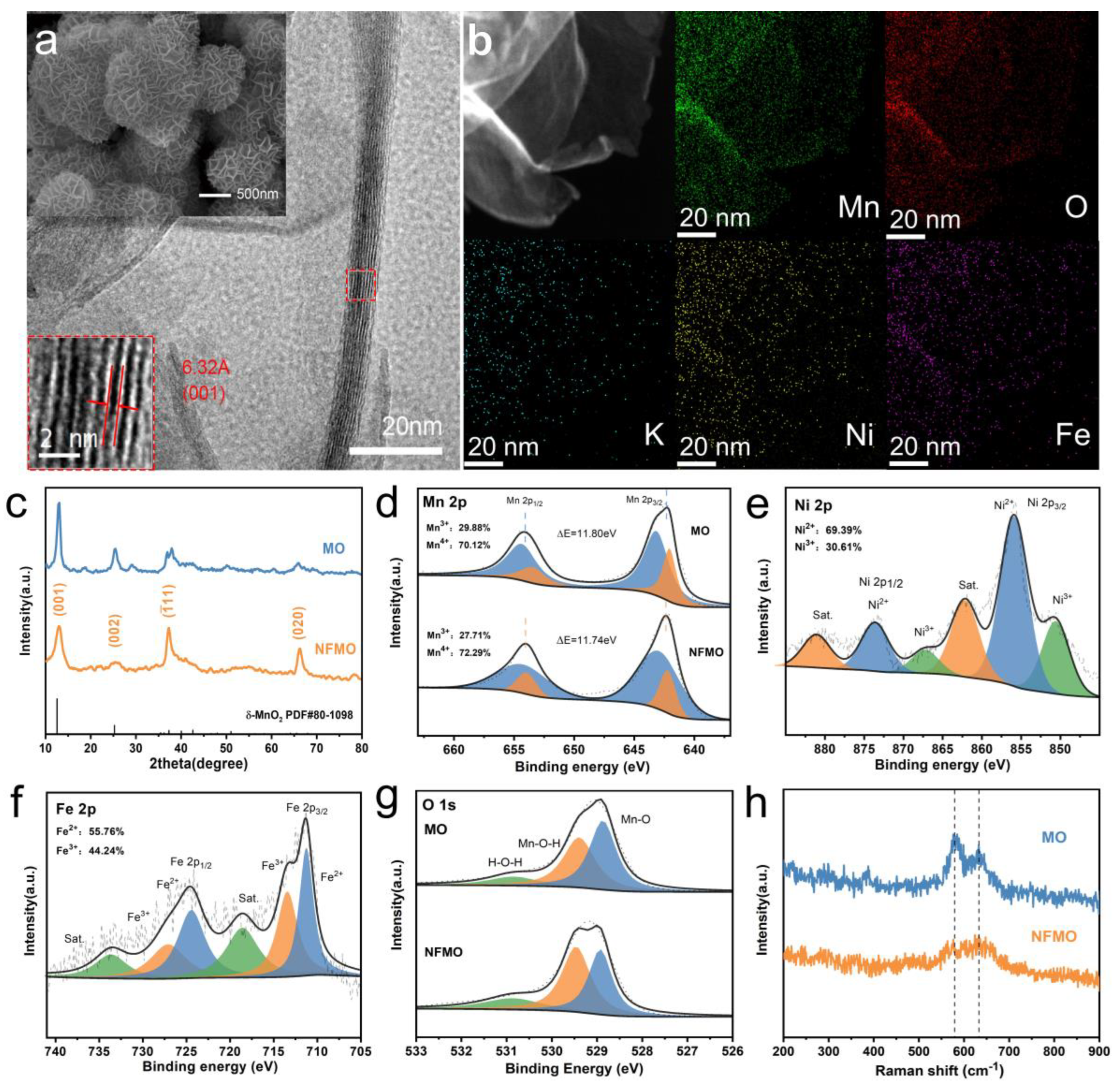
As shown in the SEM and TEM images (Figure 2a and Figure S2a), NFMO shows a nanoflower assembled by nanosheets with a thickness of about 3 nm, and the average diameter of the nanoflower is about 1 μm. Moreover, the 0.632 nm plane spacing in the HRTEM images and the diffraction ring in the selected area electron diffraction (Figure S2b) correspond to the (001) plane of δ-MnO2. The peaks (001) and (002) correspond to the layered structure of MnO2 and they are symmetric. Next, energy dispersive X-ray spectroscopy (EDX) mappings (Figure 2b) and element composition analysis (Figure S3 and Table S2) of NFMO demonstrate that K, O, Mn, Ni and Fe elements were dispersed consistently in the nanoflowers, exhibiting the presence of Ni and Fe. Figure 2c further shows the detailed crystallinity information of NFMO, where the diffraction peaks of MO and NFMO both are indexed to δ-MnO2 (JCPDS No. 80-1098) [29]. The results show that introducing a scant amount of Fe and Ni does not change the crystal structure of MO. It is worthwhile noting that the (001) and (002) peaks of NFMO are blunter and broader than MO because the crystallinity of NFMO is lower than that of MO, which originates from the introduction of crystal water and heteroatoms.
The full spectrum of X-ray photoelectron spectroscopy (XPS) measurements (Figure S4) shows the main peaks of Mn and O elements and the peaks of embedded Ni and Fe ions. As shown in Figure 2d, the energy splitting of the Mn 2p two peaks decreases, which is due to the attraction of the charge by the double substitution of low valence Ni and Fe, leading to the increase in the Mn valence state. In addition, the successful doping of Ni and Fe ions is further verified by the peaks in the XPS spectra of Ni 2p and Fe 2p, respectively (Figure 2e,f) [30]. Then, ICP tests were conducted on MO, NMO, FMO and NFMO, as shown in Table S3. The stoichiometry can be obtained by XPS analysis, combined with the results of ICP and thermogravimetric analysis (TGA) in Figure S5, where MO is K0.189MnO1.945·0.420H2O and NFMO is K0.047Ni0.081Fe0.081Mn0.838O1.683·0.837H2O. The NFMO double-substituted generated 0.262 more oxygen vacancies compared with MO. Additionally, the increase in Mn–O–H bond strength in O 1s peak is owing to the rise of the crystal water content in NFMO (Figure 2g), which is identical to the result of TGA.
The Raman spectroscopy of MO and NFMO in Figure 2h shows the two typical peaks of δ-MnO2 are 632 cm−1 and 577 cm−1, which correspond to the symmetric stretching vibration (Mn–O) of MnO6 groups and stretching vibration in the basal plane of the MnO6 sheets. In comparison to MO, the lower strength and wider width of the two bonds of NFMO are attributed to lattice defects, which confirms the generation of oxygen vacancies. Based on the above characterization results, it is proven that layered NFMO nanoflowers with oxygen defects in Figure 1a was successfully prepared.
In order to understand the performance breakthrough that can be brought about by doping Ni and Fe, NFMO is used as the cathode material of AZIBs for electrochemical testing. As shown in Figure 3a, under different current densities, the discharge-specific capacity of NFMO is well above that of NMO, FMO and MO. Especially at 3 A g−1 current density, the discharge-specific capacity of NFMO can reach 181 mA h g−1, while MO only provides 77.5 mA h g−1. When the current density returns to 0.1 A g−1, the specific capacity of NFMO can deliver 382 mA h g−1 at the 50th cycle. The long-term cycling performance at a current density of 1 A g−1 is shown in Figure S6, and the specific capacity retention of the NFMO cathode after 800 cycles was 87.9%. Furthermore, in Figure 3b, it can be observed that the constant current charge/discharge curve of NFMO shows two different discharge platforms near 1.4 V and 1.3 V, which correspond to the embedding of H+ and Zn2+, respectively.
CV tests of NFMO anode and MO cathode were carried out at different scanning rates from 0.5 mV to 1.5 mV. With the increase in scanning rate, the peaks in the CV curve begin to widen and keep the same shape. In general, the relationship between peak current (i) and scanning rate (υ) can be described by the following equation [31]:
where a is a constant, is the peak current, is the scanning rate, and b is considered the slope of the fitting line. When the b value is within 0.5–1, it indicates diffusion controlled zinc storage process, while when b value is close to 1.0, it means capacitance controlled charge storage behavior. By fitting the curves in Figure 3c and Figure S7a, it can be obtained that the corresponding b values of the four peaks are 0.755, 0.627, 0.582 and 0.647, respectively (Figure 3d and Figure S7b). Therefore, according to the above definition, the linear fit b value of NFMO stands between 0.5 and 0.8, which implies that the electrochemical reaction process of NFMO is organized by the combination of diffusion control and capacitance control. Then, the contribution of pseudo capacitance is quantitatively analyzed by the following equation: [32]. As shown in the shaded area in Figure 3e, the capacitive attribution was assessed to be 54.34% at a scanning rate of 1 mV s−1. In addition, as shown in Figure 3f and Figure S7d, the capacitance contribution of NFMO is greatly improved compared to MO, and increases with the increase in scanning rates.
As shown in Figure 4a, GITT was used to analyze the ion diffusion coefficient of NFMO electrode, which can further judge the influence of Ni and Fe ions insertion on the ion diffusion coefficient of materials. NFMO and MO show two different diffusion coefficient stages in the discharge process. These two stages correspond to two discharge platforms of the GCD curve, respectively, the diffusion of H+ and the diffusion of Zn2+, which occur mainly in the tunnel and interlayer. The diffusion coefficient of MO cathode is in the range of 10−15 to 10−10 cm2 s−1, which is well below the diffusion coefficient of NFMO cathode (10−13 to 10−8 cm2 s−1) (Figure S8), demonstrating the excellent electrochemical kinetics of NFMO cathode for AZIBs [33].
The fitting results of EIS are shown in Figure 4b. The ohmic resistance (Rs) and charge-transfer resistance (Rct) of NFMO are 1.75 Ω and 77.1 Ω, respectively, which are much lower than those of most Zn//MnO2 batteries, such as the ohmic resistance (Rs = 3.15 Ω) and charge transfer resistance (Rct = 118.1 Ω) of undoped MO [34]. As shown in Figure S10, the electronic conductivity of MO and NFMO was obtained by analyzing the voltage-current curve, where the conductivity of NFMO material is 0.1012 S m−1, and the conductivity of MO is 1.3588 × 10⁻⁴ S m−1. The above electrochemical test results indicated that the extremely excellent ion diffusion rate and electrical conductivity of NFMO cathode benefited from the optimization of band structure and charge distribution caused by Ni and Fe doping.
The evolution of the valence state, morphology and element content of NFMO during the discharge/charge cycle investigated by ex situ XPS and SEM. Figure 4c presents that a large number of flakes continuously appear on the electrode surface during the discharge process and gradually disappear during the charging process, which should be caused by the extraction/insertion of H+ [35]. When the discharge voltage achieves 0.9 V, the Zn element and S element are largely and evenly distributed in the SEM EDS mapping of the cathode (Figure S11), while after the charge voltage reaches 1.8 V, there exist only a small amount of Zn element and S element along with rich Mn element. This is related to the production of Zn4(OH)6(SO4)·5H2O (ZOSH) caused by the insertion of H+ [36]. Additionally, the reoccurrence and disappearance of ZOSH during the second discharge and charging process indicated that this process is highly reversible [37]. Next, the electrode was pretreated with dilute sulfuric acid to remove ZOSH and characterized by ex situ XPS. From the Zn 2p spectra (Figure 4d), it can be proved that the intercalation/deintercalation of Zn2+ is also a reversible process. It is observed from the Mn 2p spectrum shown in Figure 4e that there are Mn4+ and Mn3+ in the charged state, and they decrease sharply in the discharged state. In the O 1s spectrum (Figure 4f), the strength of the Mn–O–H bond is high during discharge and decreases after charging [38]. All these prove the co-intercalation of H+ and Zn2+.
4. Conclusions
In conclusion, we have modified δ-MnO2 the cathode for AZIBs via a Ni/Fe bimetallic ion-doping strategy, and DFT calculation proved that the energy band structure and electronic state were optimized due to the introduction of Ni2+ and Fe3+. In addition, it is confirmed that the co-doping of Ni and Fe ions effectively enhanced the ionic diffusion rate, electronic conductivity and reaction kinetics of materials based on the advanced characterization technology and theoretical analysis. When used as cathode materials in AZIBs, the NFMO cathode material exhibited excellent electrochemical performance in the field of high capacity (382 mA h g−1 at 0.1 A g−1), superior rate capability (181 mA h g−1 at 3 A g−1) and excellent cycling stability (87.9% capacity retention after 800 cycles at 1 A g−1). Considering the improved electrochemical performance of our NFMO electrode materials, the introduction of bimetallic dopants into materials provides an alternative solution for high-performance aqueous zinc-ion batteries.
Supplementary Materials
The following supporting information can be downloaded at: https://www.mdpi.com/article/10.3390/batteries9010050/s1, Figure S1: (a–f) six structural models for the first-principles calculations: (a) MnO2, (b) Ni-MnO2, (c) Fe-MnO2, (d) Ni-Fe-MnO2 (1-1), (e) Ni-Fe-MnO2 (1-2), (f) Ni-Fe-MnO2 (1-3); Figure S2: (a) TEM images and (b) SAED patterns of the NFMO sample; Figure S3: EDS analysis result for the marked area of TEM; Figure S4: XPS characterization of survey spectrum; Figure S5: exact molecular formula of δ-MnO2 based on the TGA, XPS and ICP results. (a) δ-MnO2 without Ni-doping: K0.189MnO1.945·0.420H2O, (b) δ-MnO2 with Ni and Fe-doping: K0.047Ni0.081Fe0.081Mn0.838O1.683·0.837H2O; Figure S6: cycling performance and the corresponding coulombic efficiency of NFMO at 1.0A g−1; Figure S7: (a) CV curves of the MO electrode at various scan rates. (b) The corresponding plots of log (current) vs. log (scan rate) of MO at each redox peak, and corresponding values. (c) Capacitive and diffusion-controlled percentage of MO at a scan rate of 1 mV s−1. (d) Contribution ratios of the capacitive capacities and diffusion-controlled capacities in the MO electrode; Figure S8: GITT curves and diffusion coefficients calculated of MO at charge/discharge states; Figure S9: equivalent circuit model; Figure S10: Voltage-current curve of MO and NFMO; Figure S11: (a) images for SEM and elemental mapping images of NFMO discharged to 0.9 V in the first cycle. (b) Images for SEM and elemental mapping images of NFMO charged to 1.8 V in the first cycle; Table S1: the minimum formation energy for three different NFMO structural models; Table S2: element composition analysis of NFMO; Table S3: ICP analysis of the four cathode materials (MO, NMO, FMO and NFMO); Table S4: Comparison of cathode performance in aqueous ZIBs between this work and other recent reports [5,9,18,31,37,39].
Author Contributions
Conceptualization, resources, supervision, project administration and funding acquisition: L.Z. and Q.A.; methodology, validation, formal analysis and investigation: F.G., W.S. and B.J.; software: B.J.; data curation: F.G.; writing—original draft preparation: F.G. and B.J.; writing—review and editing, F.G., B.J. and Z.X.; F.G., W.S. and B.J. contributed equally to this work. All authors have read and agreed to the published version of the manuscript.
Funding
This research was funded by National Natural Science Foundation of China, grant number 52172231, 51972259 and U1804253; the Natural Science Foundation of Hubei Province (2022CFA087); Industrialization Project of Xiangyang Technology Transfer Center of Wuhan University of Technology (WXCJ-20220017); National Natural Science Foundation of China (22109123); Hainan Provincial Joint Project of Sanya Yazhou Bay Science and Technology City (2021JJLH0069).
Data Availability Statement
The data that support the findings of this study are available from the corresponding author upon reasonable request.
Conflicts of Interest
The authors declare no conflict of interest.
References
- Jia, X.; Liu, C.; Neale, Z.G.; Yang, J.; Cao, G. Active Materials for Aqueous Zinc Ion Batteries: Synthesis, Crystal Structure, Morphology, and Electrochemistry. Chem. Rev. 2020, 120, 7795–7866. [Google Scholar] [CrossRef] [PubMed]
- Rodriguez-Romero, J.; Larramendi, R.d.I.; Goikolea, E. Nanostructured Manganese Dioxide for Hybrid Supercapacitor Electrodes. Batteries 2022, 8, 263. [Google Scholar] [CrossRef]
- Liu, G.; Wang, N.; Qi, F.; Lu, X.; Liang, Y.; Sun, Z. Novel Ni–Ge–P anodes for lithium-ion batteries with enhanced reversibility and reduced redox potential. Inorg. Chem. Front. 2023. [Google Scholar] [CrossRef]
- Liu, G.; Yang, Y.; Lu, X.; Qi, F.; Liang, Y.; Trukhanov, A.; Wu, Y.; Sun, Z.; Lu, X. Fully Active Bimetallic Phosphide Zn(0.5)Ge(0.5)P: A Novel High-Performance Anode for Na-Ion Batteries Coupled with Diglyme-Based Electrolyte. ACS Appl. Mater. Interfaces 2022, 14, 31803–31813. [Google Scholar] [CrossRef] [PubMed]
- Zhao, Q.; Song, A.; Zhao, W.; Qin, R.; Ding, S.; Chen, X.; Song, Y.; Yang, L.; Lin, H.; Li, S.; et al. Boosting the Energy Density of Aqueous Batteries via Facile Grotthuss Proton Transport. Angew. Chem. Int. Ed. 2021, 60, 4169–4174. [Google Scholar] [CrossRef] [PubMed]
- Zhang, T.; Tang, Y.; Guo, S.; Cao, X.; Pan, A.; Fang, G.; Zhou, J.; Liang, S. Fundamentals and perspectives in developing zinc-ion battery electrolytes: A comprehensive review. Energy Environ. Sci. 2020, 13, 4625–4665. [Google Scholar] [CrossRef]
- Mo, F.; Cui, M.; Yang, L.; Lei, H.; Chen, S.; Wei, J.; Kang, L. Phase-Transformation-Activated MnCO3 as Cathode Material of Aqueous Zinc-Ion Batteries. Batteries 2022, 8, 239. [Google Scholar] [CrossRef]
- Gao, F.; Mei, B.; Xu, X.; Ren, J.; Zhao, D.; Zhang, Z.; Wang, Z.; Wu, Y.; Liu, X.; Zhang, Y. Rational design of ZnMn2O4 nanoparticles on carbon nanotubes for high-rate and durable aqueous zinc-ion batteries. Chem. Eng. J. 2022, 448, 137742. [Google Scholar] [CrossRef]
- Liao, Y.; Yang, C.; Xu, Q.; Zhao, W.; Zhao, J.; Wang, K.; Chen, H. Ag-Doping Effect on MnO2 Cathodes for Flexible Quasi-Solid-State Zinc-Ion Batteries. Batteries 2022, 8, 267. [Google Scholar] [CrossRef]
- Dai, Y.; Liao, X.; Yu, R.; Li, J.; Li, J.; Tan, S.; He, P.; An, Q.; Wei, Q.; Chen, L.; et al. Quicker and More Zn2+ Storage Predominantly from the Interface. Adv. Mater. 2021, 33, e2100359. [Google Scholar] [CrossRef]
- Wang, W.; Xiong, F.; Zhu, S.; Chen, J.; Xie, J.; An, Q. Defect engineering in molybdenum-based electrode materials for energy storage. eScience 2022, 2, 278–294. [Google Scholar] [CrossRef]
- Liang, Y.; Dong, H.; Aurbach, D.; Yao, Y. Publisher Correction: Current status and future directions of multivalent metal-ion batteries. Nat. Energy 2020, 5, 822. [Google Scholar] [CrossRef]
- Liu, X.; Cao, Y.; Sun, J. Defect Engineering in Prussian Blue Analogs for High-Performance Sodium-Ion Batteries. Adv. Energy Mater. 2022, 12, 2202532. [Google Scholar] [CrossRef]
- Zhu, S.; Dai, Y.; Li, J.; Ye, C.; Zhou, W.; Yu, R.; Liao, X.; Li, J.; Zhang, W.; Zong, W.; et al. Cathodic Zn underpotential deposition: An evitable degradation mechanism in aqueous zinc-ion batteries. Sci. Bull. 2022, 67, 1882–1889. [Google Scholar] [CrossRef] [PubMed]
- Wang, W.; Huang, G.; Wang, Y.; Cao, Z.; Cavallo, L.; Hedhili, M.N.; Alshareef, H.N. Organic Acid Etching Strategy for Dendrite Suppression in Aqueous Zinc-Ion Batteries. Adv. Energy Mater. 2022, 12, 2102797. [Google Scholar] [CrossRef]
- Zhang, J.; Kim, J.B.; Zhang, J.; Lee, G.H.; Chen, M.; Lau, V.W.; Zhang, K.; Lee, S.; Chen, C.L.; Jeon, T.Y.; et al. Regulating Pseudo-Jahn-Teller Effect and Superstructure in Layered Cathode Materials for Reversible Alkali-Ion Intercalation. J. Am. Chem. Soc. 2022, 144, 7929–7938. [Google Scholar] [CrossRef] [PubMed]
- Zheng, Z.; Yang, G.; Yao, J.; Li, J.; Zheng, J.; Wu, Z.; Gan, Y.; Wang, C.; Lv, L.; Wan, H.; et al. High-valence molybdenum promoted proton migration and inhibited dissolution for long-life aqueous Zn-MnO2 batteries. Appl. Surf. Sci. 2022, 592, 153335. [Google Scholar] [CrossRef]
- Ding, S.; Liu, L.; Qin, R.; Chen, X.; Song, A.; Li, J.; Li, S.; Zhao, Q.; Pan, F. Progressive “Layer to Hybrid Spinel/Layer” Phase Evolution with Proton and Zn2+ Co-intercalation to Enable High Performance of MnO2-Based Aqueous Batteries. ACS Appl. Mater. Interfaces 2021, 13, 22466–22474. [Google Scholar] [CrossRef]
- An, Y.; Tan, S.; Liu, Y.; Zhu, K.; Hu, L.; Rong, Y.; An, Q. Designs and applications of multi-functional covalent organic frameworks in rechargeable batteries. Energy Storage Mater. 2021, 41, 354–379. [Google Scholar] [CrossRef]
- Jing, F.; Liu, Y.; Shang, Y.; Lv, C.; Xu, L.; Pei, J.; Liu, J.; Chen, G.; Yan, C. Dual ions intercalation drives high-performance aqueous Zn-ion storage on birnessite-type manganese oxides cathode. Energy Storage Mater. 2022, 49, 164–171. [Google Scholar] [CrossRef]
- Lv, W.; Meng, J.; Li, Y.; Yang, W.; Tian, Y.; Lyu, X.; Duan, C.; Ma, X.; Wu, Y. Inexpensive and eco-friendly nanostructured birnessite-type δ-MnO2: A design strategy from oxygen defect engineering and K+ pre-intercalation. Nano Energy 2022, 98, 107274. [Google Scholar] [CrossRef]
- Pu, X.; Li, X.; Wang, L.; Maleki Kheimeh Sari, H.; Li, J.; Xi, Y.; Shan, H.; Wang, J.; Li, W.; Liu, X.; et al. Enriching Oxygen Vacancy Defects via Ag–O–Mn Bonds for Enhanced Diffusion Kinetics of delta-MnO2 in Zinc-Ion Batteries. ACS Appl. Mater. Interfaces 2022, 14, 21159–21172. [Google Scholar] [CrossRef]
- Xiong, F.; Tan, S.; Yao, X.; An, Q.; Mai, L. Crystal defect modulation in cathode materials for non-lithium ion batteries: Progress and challenges. Mater. Today 2021, 45, 169–190. [Google Scholar] [CrossRef]
- Zhang, M.; Wu, W.; Luo, J.; Zhang, H.; Liu, J.; Liu, X.; Yang, Y.; Lu, X. A high-energy-density aqueous zinc–manganese battery with a La–Ca co-doped ε-MnO2 cathode. J. Mater. Chem. A 2020, 8, 11642–11648. [Google Scholar] [CrossRef]
- Jiang, B.; Yang, T.; Wang, T.; Chen, C.; Yang, M.; Yang, X.; Zhang, J.; Kou, Z. Edge stimulated hydrogen evolution reaction on monodispersed MXene quantum dots. Chem. Eng. J. 2022, 442, 136119. [Google Scholar] [CrossRef]
- Chuai, M.; Yang, J.; Wang, M.; Yuan, Y.; Liu, Z.; Xu, Y.; Yin, Y.; Sun, J.; Zheng, X.; Chen, N.; et al. High-performance Zn battery with transition metal ions co-regulated electrolytic MnO2. eScience 2021, 1, 178–185. [Google Scholar] [CrossRef]
- Zhang, Y.; Deng, S.; Luo, M.; Pan, G.; Zeng, Y.; Lu, X.; Ai, C.; Liu, Q.; Xiong, Q.; Wang, X.; et al. Defect Promoted Capacity and Durability of N-MnO2-x Branch Arrays via Low-Temperature NH3 Treatment for Advanced Aqueous Zinc Ion Batteries. Small 2019, 15, e1905452. [Google Scholar] [CrossRef]
- Xiao, Z.; Xia, F.; Xu, L.; Wang, X.; Meng, J.; Wang, H.; Zhang, X.; Geng, L.; Wu, J.; Mai, L. Suppressing the Jahn–Teller Effect in Mn-Based Layered Oxide Cathode toward Long-Life Potassium-Ion Batteries. Adv. Funct. Mater. 2021, 32, 2108244. [Google Scholar] [CrossRef]
- Long, F.; Xiang, Y.; Yang, S.; Li, Y.; Du, H.; Liu, Y.; Wu, X.; Wu, X. Layered manganese dioxide nanoflowers with Cu2+ and Bi3+ intercalation as high-performance cathode for aqueous zinc-ion battery. J. Colloid Interface Sci. 2022, 616, 101–109. [Google Scholar] [CrossRef]
- Zhai, X.Z.; Qu, J.; Hao, S.M.; Jing, Y.Q.; Chang, W.; Wang, J.; Li, W.; Abdelkrim, Y.; Yuan, H.; Yu, Z.Z. Layered Birnessite Cathode with a Displacement/Intercalation Mechanism for High-Performance Aqueous Zinc-Ion Batteries. Nano-Micro Lett. 2020, 56, 1–15. [Google Scholar] [CrossRef] [Green Version]
- Li, J.; Luo, N.; Kang, L.; Zhao, F.; Jiao, Y.; Macdonald, T.J.; Wang, M.; Parkin, I.P.; Shearing, P.R.; Brett, D.J.L.; et al. Hydrogen-Bond Reinforced Superstructural Manganese Oxide As the Cathode for Ultra-Stable Aqueous Zinc Ion Batteries. Adv. Energy Mater. 2022, 12, 2201840. [Google Scholar] [CrossRef]
- Wei, Q.; Schibli, E.; Chen, B.; Holdcroft, S. Enhanced lifetime of the zinc–iodine batteries using hydrocarbon cation-exchange polymer-protected zinc anodes. Energy Adv. 2022, 1, 606–612. [Google Scholar] [CrossRef]
- Fang, G.; Zhu, C.; Chen, M.; Zhou, J.; Tang, B.; Cao, X.; Zheng, X.; Pan, A.; Liang, S. Suppressing Manganese Dissolution in Potassium Manganate with Rich Oxygen Defects Engaged High-Energy-Density and Durable Aqueous Zinc-Ion Battery. Adv. Funct. Mater. 2019, 29, 1808375. [Google Scholar] [CrossRef]
- Guo, S.; Liang, S.; Zhang, B.; Fang, G.; Ma, D.; Zhou, J. Cathode Interfacial Layer Formation via in Situ Electrochemically Charging in Aqueous Zinc-Ion Battery. ACS Nano 2019, 13, 13456–13464. [Google Scholar] [CrossRef] [PubMed]
- Wang, H.; Liang, M.; Gao, J.; Ma, C.; He, Z.; Zhao, Y.; Miao, Z. Robust structural stability of flower-like δ-MnO2 as cathode for aqueous zinc ion battery. Colloids Surf. A 2022, 643, 128804. [Google Scholar] [CrossRef]
- Zhang, T.; Tang, Y.; Fang, G.; Zhang, C.; Zhang, H.; Guo, X.; Cao, X.; Zhou, J.; Pan, A.; Liang, S. Electrochemical Activation of Manganese-Based Cathode in Aqueous Zinc-Ion Electrolyte. Adv. Funct. Mater. 2020, 30, 2002711. [Google Scholar] [CrossRef]
- Fenta, F.W.; Olbasa, B.W.; Tsai, M.-C.; Weret, M.A.; Zegeye, T.A.; Huang, C.-J.; Huang, W.-H.; Zeleke, T.S.; Sahalie, N.A.; Pao, C.-W.; et al. Electrochemical transformation reaction of Cu–MnO in aqueous rechargeable zinc-ion batteries for high performance and long cycle life. J. Mater. Chem. A 2020, 8, 17595–17607. [Google Scholar] [CrossRef]
- Zhou, S.; Wu, X.; Du, H.; He, Z.; Wu, X.; Wu, X. Dual metal ions and water molecular pre-intercalated delta-MnO2 spherical microflowers for aqueous zinc ion batteries. J. Colloid Interface Sci. 2022, 623, 456–466. [Google Scholar] [CrossRef]
- Xu, J.W.; Gao, Q.L.; Xia, Y.M.; Lin, X.S.; Liu, W.L.; Ren, M.M.; Kong, F.G.; Wang, S.J.; Lin, C. High-performance reversible aqueous zinc-ion battery based on iron-doped alpha-manganese dioxide coated by polypyrrole. J. Colloid Interface Sci. 2021, 598, 419–429. [Google Scholar] [CrossRef] [PubMed]
Figure 1.
(a) Synthesis schematic of NFMO, (b) band structures, (c) PDOS and (d) charge density of the four theoretical calculation structural models (MO, FMO, NMO and NFMO, red represents oxygen, purple represents manganese, yellow represents iron, and silver represents nickel).
Figure 1.
(a) Synthesis schematic of NFMO, (b) band structures, (c) PDOS and (d) charge density of the four theoretical calculation structural models (MO, FMO, NMO and NFMO, red represents oxygen, purple represents manganese, yellow represents iron, and silver represents nickel).

Figure 2.
(a) SEM, TEM and HRTEM images of NFMO. (b) EDS elemental mapping of the NFMO sample. (c) XRD patterns of NFMO and MO. (d–g) XPS characterization of NFMO and MO: (d) Mn 2p spectrum, (e) Ni 2p spectrum, (f) Fe 2p spectrum, (g) O 1s spectrum. (h) Raman spectrum.
Figure 2.
(a) SEM, TEM and HRTEM images of NFMO. (b) EDS elemental mapping of the NFMO sample. (c) XRD patterns of NFMO and MO. (d–g) XPS characterization of NFMO and MO: (d) Mn 2p spectrum, (e) Ni 2p spectrum, (f) Fe 2p spectrum, (g) O 1s spectrum. (h) Raman spectrum.

Figure 3.
(a) Rate performance of the four cathodes. (b) Charge/discharge profiles of NFMO at different current densities from 0.1 to 3 A g−1. (c) CV curves of the NFMO electrode at various scan rates. (d) The corresponding plots of log (current) vs. log (scan rate) of MO at each redox peak, and corresponding b values. (e) Capacitive and diffusion-controlled percentage of NFMO at a scan rate of 1 mV s−1. (f) Contribution ratios of the capacitive capacities and diffusion-controlled capacities in the NFMO electrode.

Figure 4.
(a) GITT curves and diffusion coefficients calculated for NFMO at charge/discharge states. (b) The fitted EIS data of NFMO and NKMO cathodes. (c) Ex situ SEM images of the first two cycles of NFMO in different discharge/charge states. (d) Zn 2p, (e) Mn 2p, and (f) O 1s in the fully discharged and charged states.

Disclaimer/Publisher’s Note: The statements, opinions and data contained in all publications are solely those of the individual author(s) and contributor(s) and not of MDPI and/or the editor(s). MDPI and/or the editor(s) disclaim responsibility for any injury to people or property resulting from any ideas, methods, instructions or products referred to in the content. |
© 2023 by the authors. Licensee MDPI, Basel, Switzerland. This article is an open access article distributed under the terms and conditions of the Creative Commons Attribution (CC BY) license (https://creativecommons.org/licenses/by/4.0/).
Share and Cite
MDPI and ACS Style
Gao, F.; Shi, W.; Jiang, B.; Xia, Z.; Zhang, L.; An, Q. Ni/Fe Bimetallic Ions Co-Doped Manganese Dioxide Cathode Materials for Aqueous Zinc-Ion Batteries. Batteries 2023, 9, 50. https://doi.org/10.3390/batteries9010050
AMA Style
Gao F, Shi W, Jiang B, Xia Z, Zhang L, An Q. Ni/Fe Bimetallic Ions Co-Doped Manganese Dioxide Cathode Materials for Aqueous Zinc-Ion Batteries. Batteries. 2023; 9(1):50. https://doi.org/10.3390/batteries9010050
Chicago/Turabian StyleGao, Feifei, Wenchao Shi, Bowen Jiang, Zhenzhi Xia, Lei Zhang, and Qinyou An. 2023. "Ni/Fe Bimetallic Ions Co-Doped Manganese Dioxide Cathode Materials for Aqueous Zinc-Ion Batteries" Batteries 9, no. 1: 50. https://doi.org/10.3390/batteries9010050
Note that from the first issue of 2016, this journal uses article numbers instead of page numbers. See further details here.