PIC16F84 Introduction
The 16F84 is deserves looking at because it is the GranDaddy of PIC
Microcontrollers but you should not use it for new designs (see Below)...
The PIC16F84 is a the most well known and most well used of all the PIC microcontrollers - it is used in numerous projects that you can find across the web.
Even though the 16F84 is getting on a bit, it is one of the most popular of
the PIC microcontrollers and there are hundreds of circuits for it on the web
but it does have limited memory, RAM and peripherals (See diagram below). As of
2015 microchip are recommending that you use 16F84A instead of 16F84 with the
only difference being that the A-version runs at 20MHz using a 20MHz crystal
(the non-A version runs at 10MHz crystal speed only).
It is an 8 bit mid-range microcontroller having 1024 words of program memory,
68 bytes of RAM and 64 bytes of long term EEPROM storage and a single
peripheral - an 8 bit timer - Timer0. The real innovation of this device is
that it can be re-programmed using ICSP in circuit - and the interesting thing
is that this same scheme is used in all PIC devices proving that the design was
and is good from the start. The same can be said of Timer0 which is also used
throughout the PIC family ranges, although in 18F devices you can set a control
bit that turns it into a 16 bit timer. Of course the 8-bit implementation in
that device is still the same as the 16F84!
ICSP
The most useful feature of this microcontroller is that it's flash based so
it can be re-programmed many times. In addition if you design the circuit
correctly you can re-program it in-circuit without removing the chip using
(ICSP) In Circuit Serial Programming.
Warning the 16F84 is obsolete.
The 16F88,1FF628,16F627 have the same pinout
and are cheaper!
(There are also many other similar chips with different RAM/EPROM/internal peripherals).
Even so if you already have a PIC16F84 then this introduction will show
you how to program it with a ICSP programmer. For a comparison between the
16F84 and some other PIC micros (including the 16F88) you can compare bubble
diagrams showing PIC features visually here.
In fact the 16F88 is a good PIC micro to progress onto after starting out on
the 16F84 as the 16F88 is backwards compatible with the 16F84 -it has the same
number of pins and same pin functions. Some pins are more flexible but still
backwards compatible with the 16F84.
Note: You can't easily go from a 16F88
back to a 16F84A, as the 16F88 lets you use pins in a more flexible
manner e.g. the 16F88 has an internal oscillator and you can use the crystal
oscillator pins either for an external crystal oscillator (as in the 16F84) or
as normal I/O pins. This lets the 16F88 have 16 I/O pins as compared to the
16F84 with 13 I/O pins.
For this introduction you need a PIC programmer with an ICSP output connector
e.g. PICKit3.
You'll also need to download the C compiler for source code re-compilation
(if you want the re-compile code). The compiler is free for the small amounts
of code used here.
Jump to Circuit diagram.
| PIC 16F84 Index |
| Features |
| Programming |
| ICSP Connection |
| Power Supply |
| Oscillator modes |
| Starter circuit and software |
Before you start have a look at the following for background info:
- Programming with PIC ICSP (In Circuit Serial Programming).
- PIC ICSP signals and 'real' circuit.
- General purpose ICSP programmer circuit (this is a parallel port programmer) - For USB ports use a PICKit3 or PICKit2.
- MikroC compiler (Use the Free [<2k] download link).
- General usage of the MikroC Compiler.
PIC16F84 Features
The 16F84 is packaged in an 18 pin chip and although it has limited
peripherals it is usable in many circuits. Here are its features and a short
comparison.
| Comparison | 16F84 | 16F88 |
| Program Memory | 1024 Words | 4096 Words |
| RAM | 68 Bytes | 368 Bytes |
| EEPROM | 64 Bytes | 256 Bytes |
| I/O PINS | 13 | 16 |
| PERIPHERALS | 1 | 9 |
| List of peripherals | Timer:1 | Timers:3, ADC 7 i/ps, 2 Analogue comparators, CCP,SSP, USART |
The following bubble diagram shows the major peripherals and features of the
16F84 in a visual format:
16F84

Note: You can compare this chip (using
bubble diagrams) to some others used on this site by clicking here.
PIC16F84 Programming
You can find a programmer circuit
hereand information on using ICPROG here.
PIC16F84 : ICSP connections:

PIC16F84 Power Supply
If you don't have a bench power supply then you can use this circuit.
 x
x
All you will need is a power supply block with dc output (greater than
8V and no more than 35V) or a 9V battery to plug into CN1.
Note: It is best to use the 5V power supply circuit as it not only correctly
regulates the dc voltage but it protects your PIC chip. The input voltage can
go up to 35V without damaging the 7805 (although the power dissipated by the
7805 will increase for higher input voltages i.e.it wail get hot!) .

PIC16F84 Oscillator modes
There are four oscillator modes either using an resistor and capacitor pair
or a crystal.
PIC16F84 Flashing an LED

Note: The LED current limiter resistor
(1k) is not ideal it just lets you see the led (you don't need maximum current
to see it) - Replace the 1k with a 220 if you want brighter output.
PIC16F84 Flashing LED
The following code flashes the LED.
Download the source file and hex files here.
You can use the hex file directly to program the 16F84 then it will flash the
led on and off or you can re-compile the files using the
Mikroelectronika compiler MikroC.
Some of the PIC16F84 C source code is :
| ////////////////////////////////////////////////////////////////////// // Start here for PIC16F84 led flash // void main() { unsigned short pa=0; unsigned int i; PORTA = 0; TRISA = 0; // o/p - sets analogue pins to digital output TRISB = 0; PORTB = 0; while(1) { pa=~pa; if (pa) { setBit(PORTB,3); } else { resBit(PORTB,3); } Delay_ms(100); } ; // infinite while loop } |
First of all the ports are initialized using TRISA, TRISB which set up the
direction of pins for each port - in common with all the other PIC Micros you
can change the port direction at any time using a TRIS keyword (which is just
another register location).
Setting a bit in the TRIS register to zero sets the pin direction to an output.
Here all bits are zero for TRISA and TRISB so all PORTA and PORTB bits are
set as outputs. Then PORTA and PORTB are initialized to logic level zero.
As you can see main() is a very simple it alternately sets and resets bit 3 of
PORTB
Try changing the delay time in the delay_ms statements to a smaller or larger
value, re-compile and re-program the chip to see the effect.
This gives you the basis for using the PIC16F84 so that you can move on to more
complex projects.
Site Map | Terms of Use
Search:
Recent Articles
-
Arduino IR Remote: A Beginners Project for Infrared Control
 Introducing Arduino IR remote control [Beginners Guide]. How to build a circuit to receive and transmit IR codes through a hands-on project [full code included].
 -
Adding Arduino RFID reader Scanning to Your Projects
 This beginners tutorial gives you a complete step-by-step guide for interfacing an Arduino Uno with the MFRC522 RFID reader module. There is one problem with most circuits out there...
 -
Arduino Hall Effect Sensor Tutorial: Detect Magnets Easily
 Arduino Hall Effect Sensor: Add magnetic sensing superpowers to your Arduino projects with an easy-to-use hall effect sensor. With full code and layout...
 -
Logic Level Converter: Easily Convert between 5V and 3V
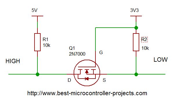 Logic Level Converter: How to create a bi-directional interface that automatically translates voltage levels using a subtle MOSFET property...
 -
Arduino Ultrasonic Sensors: A Beginner's Guide to the HC SR04
 A step-by-step guide to using Arduino ultrasonic sensors for object detection and distance measurement. Details the libraries you need, example code and circuit diagram.
 -
Arduino Humidity Sensor: A Beginners Tutorial on the DHT11 sensor
 Get started with an Arduino humidity sensor using the DHT11, which reports both humidity and temperature. Complete guide with full code for using this sensor
you so so so much
for all the information
you have provided in
your site it's
SUPERB and FANTASTIC."
- Ranish Pottath
the best and my favorite.
I find here many useful
projects and tips."
- Milan
bursach<at>gmail.com<
very, very easy and nice
to navigate!"
- Matt
matt_tr<at>
wolf359.cjb.net
"I am a newbie to PIC
and I wanted to say
how great your
site has been for me."
- Dave
de_scott<at>bellsouth.net
and perfect work.
congratulations."
- Suresh
integratredinfosys<at>
yahoo.com
words to define
yourweb site.
Very useful, uncovered,
honest and clear.
Thanks so much for
your time and works.
Regards."
- Anon
Comments
Have your say about what you just read! Leave me a comment in the box below.
Don’t see the comments box? Log in to your Facebook account, give Facebook consent, then return to this page and refresh it.