
Create successful ePaper yourself
Turn your PDF publications into a flip-book with our unique Google optimized e-Paper software.
Warning Before InstallEnglishPower off the Network Camera assoon as it is found smoking or smeltunusual.Keep the Network Camera away fromthe water. If the Network Camera iswet, power off immediately.Contact your distributor when such caseshappen.Contact your distributor when such caseshappen.Do not place the Network Cameraaround the heat sources, such astelevision or oven.Refer to your user's manual for theoperating temperature.Keep the Network Camera away fromdirect sunlight.Do not place the Network Camera inhigh humid environments.EN - 1
Do not place the Network Camera onunsteady surfaces.Do not touch the Network Camerawhen it's lightening.Do not disassemble the NetworkCamera.Do not drop the Network Camera.Do not insert any object into theNetwork Camera, such as needles.EN - 2
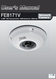
1Package ContentsEnglish<strong>FD7132</strong>Power adapterSoftware CDAlignment stickerWarranty cardQuick installation guideScrewdriverScrews and I/O connectorEN - 3
I/O1 2 3 4Audio Out Mic. In Ext. Int.3Hardware InstallationEnglishFirst, use the supplied screwdriver to detach the dome cover from the camera base. Then,follow the steps below to install the camera; either to a ceiling or to a wall.Installation TipsBefore installing the camera, look for a spot that best suits your needs. The built-in PIRsensor is designed to be triggered when a person enters its detection range. Therefore,it is crucial to install the camera at a place with the PIR sensor facing the desired direction.(The sensitivity of PIR sensor depends on object size and temperature differencesbetween the object and the background environment.)Top viewSide viewCeiling mountThrough the two holes on each side of the camera base, insertthe supplied two screws to corresponding holes and securethem with a screwdriver.Alignment stickerWall mount1. Attach the alignment sticker to the wall.2. Through the two circles on the sticker, drill two pilot holesinto the wall.3. Hammer the supplied plastic anchors into the holes.4. Align the two holes on each side of the camera base with thetwo plastic anchors on the wall, insert the supplied screws tocorresponding holes and secure them with a screwdriver.EN - 5
POWER COLLISION1 2 3 4 5LINKRECEIVEPARTITION4Network DeploymentGeneral Connection (without PoE)1. If you have external devices such as sensors and alarms, make connections from generalI/O terminal block.2. Connect the camera to a switch via a Ethernet cable.3. Connect the supplied power cable from the camera to a power outlet.1I/O1 2 3 4Audio Out Mic. In Ext. Int.1: Power2: Digital output3: Digital input4: GroundEthernet switch23EN - 6
POWER COLLISION1 2 3 4 5LINKRECEIVEPARTITIONPOWER COLLISION1 2 3 4 5LINKRECEIVEPARTITIONPower over Ethernet (PoE)EnglishWhen using a PoE-enabled switchThe camera is PoE-compliant, allowing transmission of power and data via single Ethernetcable. See the following illustration to connect the camera to a PoE-enabled switchvia Ethernet cable.PoE switchWhen using a non-PoE switch<strong>Use</strong> a PoE power injector (optional) to connect between the camera and a non-PoEswitch.PoE power injector(optional)non-PoE switchEN - 7
5Assigning <strong>IP</strong> Address1. Install the "Installation Wizard 2" under the Software Utility directory from software CD.2. The program will conduct analyses on your network environment. After your network isanalyzed, please click on the "Next" button to continue the program.InstallationWizard 23. The program will search the VIVOTEK Video Receivers, Video Servers or Network Camerason the same LAN.4. After searching, the main installer window will pop up. Click on the MAC that matches theone labeled on the bottom of your device to connect the Internet Explorer to the NetworkCamera.Network CameraModel No: <strong>FD7132</strong>MAC:0002D107258ARoHSC I0002D107258AThis device complies with part 15 of the FCC rules. Operation is subject tothe following two conditions:(1)This device may not cause harmful interference, and(2) this device must accept any interference received, including interferencethat may cause undesired operation.Pat. 6,930,709Made in TaiwanEN - 8
6Ready to <strong>Use</strong>English1. Access to the Network Camera from the Internet.2. Retrieve live video through web browsers or recording software.3. It is suggusted to select Fix Iris in the Audio and Video page (Choose Configuration >Advanced mode > Audio and video) to set up the iris at the maximum value; then followthe instructions on the next page to adjust the zoom factor and focus range. Uponcompletion, uncheck this item to enable auto iris.For further setup, please refer to user's manual on the software CD.EN - 9
7Adjusting the LensBased on the live image retrieved from the camera, adjust the camera lens by doing thefollowing:To adjust the viewing angle1. Loosen the pan screw and then turn the lens module left and right. Upon completion,tighten the pan screw.2. Loosen the tilt screws on both side of the camera and then turn the lens module up anddown. Upon completion, tighten the tilt screws.3. Loosen the image adjustment screw and then turn the lens to adjust the imageorientation. Upon completion, tighten the image adjustment screw.Rotate the screwTurn the lens11 2 3 4 Audio Out Mic. In Ext. Int.1 2 3 4 Audio Out Mic. In Ext. Int.Audio Out Mic. In Ext. Int.1 2 3 4I/OLoosenTightenLoosen2I/OTightenI/OLoosenTighten3To adjust the zoom factor and focus range1. Loosen the zoom controller and then adjust zoom factor by moving the controller left andright. Upon completion, tighten the zoom controller.2. Loosen the focus controller and then adjust focus range by moving the controller left andright. Upon completion, tighten the focus controller.Audio Out Mic. In Ext. Int.1 2 3 4I/OLoosenWNTTighten8DO NOT over tighten the controllers.Doing so would damage the structureof camera lens.EN - 10
8CompletionEnglishAttach the dome cover to camera. Secure the two dome screws with a screwdriver.Finally, make sure all parts of the camera are securely installed.The supplied screwdriver is exclusivelydesigned to match the dome screws. In caseyou will need to adjust the lens at a later time,do not discard the screwdriver.EN - 11
CopyrightP/N: 625006600G Ver.1.012008 VIVOTEK INC. All right reserved.