
You also want an ePaper? Increase the reach of your titles
YUMPU automatically turns print PDFs into web optimized ePapers that Google loves.
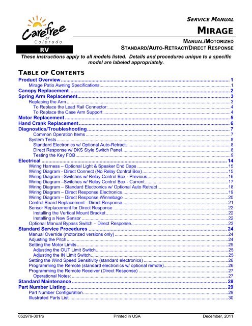
SERVICE MANUAL<br />
<strong>MIRAGE</strong><br />
MANUAL/MOTORIZED<br />
RV<br />
STANDARD/AUTO-RETRACT/DIRECT RESPONSE<br />
These instructions apply to all models listed. Details and procedures unique to a specific<br />
model are labeled appropriately.<br />
TABLE OF CONTENTS<br />
Product Overview .......................................................................................................................... 1<br />
Mirage Patio Awning Specifications ........................................................................................................ 1<br />
Canopy Replacement .................................................................................................................... 2<br />
Spring Arm Replacement .............................................................................................................. 3<br />
Replacing the Arm .................................................................................................................................. 3<br />
To Replace the Lead Rail Connector: ................................................................................................. 4<br />
To Replace the Case Arm Support ..................................................................................................... 4<br />
Motor Replacement ....................................................................................................................... 5<br />
Hand Crank Replacement ............................................................................................................. 6<br />
Diagnostics/Troubleshooting ....................................................................................................... 7<br />
Common Operation Items ................................................................................................................... 7<br />
System Tests .......................................................................................................................................... 8<br />
Standard Electronics w/ Optional Auto-Retract ................................................................................... 8<br />
Direct Response w/ DKS Style Switch Panel ...................................................................................... 8<br />
Testing the Key FOB ........................................................................................................................... 9<br />
Electrical ...................................................................................................................................... 14<br />
Wiring Harness – Optional Light & Speaker End Caps ........................................................................ 15<br />
Wiring Diagram - Direct Connect (No Relay Control Box) .................................................................... 15<br />
Wiring Diagram –Switches w/ Relay Control Box - Previous ................................................................ 16<br />
Wiring Diagram –Switches w/ Relay Control Box - Current .................................................................. 17<br />
Wiring Diagram – Standard Electronics w/ Optional Auto Retract ........................................................ 18<br />
Wiring Diagram – Direct Response Electronics .................................................................................... 19<br />
Wiring Diagram – Direct Response Winnebago ................................................................................... 20<br />
Control Board Replacement - Direct Response .................................................................................... 21<br />
Sensor Replacement for Direct Response ........................................................................................... 22<br />
Installing the Vertical Mount Bracket ................................................................................................. 22<br />
Installing a New Sensor .................................................................................................................... 22<br />
Optional Manual Bypass Switch – Direct Response ............................................................................. 23<br />
Standard Service Procedures .................................................................................................... 24<br />
Manual Override (motorized versions only) .......................................................................................... 24<br />
Adjusting the Pitch ................................................................................................................................ 24<br />
Setting the Motor Limits ........................................................................................................................ 25<br />
Adjusting the OUT Limit Switch ......................................................................................................... 25<br />
Adjusting the IN Limit Switch ............................................................................................................. 25<br />
Setting the Wind Speed Sensitivity (standard electronics) ................................................................... 26<br />
Programming the Remote (standard electronics w/ optional remote) ................................................... 26<br />
Programming the Remote Receiver (Direct Response) ....................................................................... 27<br />
Operational Notes: ............................................................................................................................ 27<br />
Standard Maintenance ................................................................................................................ 28<br />
Part Number Listing .................................................................................................................... 29<br />
Part Number Configuration ................................................................................................................... 29<br />
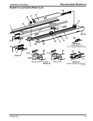
Illustrated Parts List .............................................................................................................................. 30<br />
052979-301r6 Printed in USA December, 2011
PROPRIETARY STATEMENT<br />
The Mirage Patio Awning is a product <strong>of</strong> <strong>Carefree</strong> <strong>of</strong> <strong>Colorado</strong>, located in Broomfield, <strong>Colorado</strong>, USA. The<br />
information contained in or disclosed in this document is considered proprietary to <strong>Carefree</strong> <strong>of</strong> <strong>Colorado</strong>.<br />
Every effort has been made to ensure that the information presented in the document is accurate and<br />
complete. However, <strong>Carefree</strong> <strong>of</strong> <strong>Colorado</strong> assumes no liability for errors or for any damages that result<br />
from the use <strong>of</strong> this document.<br />
The information contained in this manual pertains to the current configuration <strong>of</strong> the models listed on the<br />
title page. Earlier model configurations may differ from the information given. <strong>Carefree</strong> <strong>of</strong> <strong>Colorado</strong><br />
reserves the right to cancel, change, alter or add any parts and assemblies, described in this manual,<br />
without prior notice.<br />
<strong>Carefree</strong> <strong>of</strong> <strong>Colorado</strong> agrees to allow the reproduction <strong>of</strong> this document for use with <strong>Carefree</strong> <strong>of</strong> <strong>Colorado</strong><br />
products only. Any other reproduction or translation <strong>of</strong> this document in whole or part is strictly prohibited<br />
without prior written approval from <strong>Carefree</strong> <strong>of</strong> <strong>Colorado</strong>.<br />
SAFETY INFORMATION<br />
WARNING<br />
A WARNING INDICATES A POTENTIALLY HAZARDOUS SITUATION WHICH , IF NOT AVOIDED, COULD RESULT IN<br />
DEATH OR SERIOUS INJURY AND/OR MAJOR PROPERTY DAMAGE.<br />
CAUTION<br />
A CAUTION INDICATES A POTENTIALLY HAZARDOUS SITUATION THAT MAY CAUSE MINOR TO MODERATE<br />
PERSONAL INJURY AND/OR PROPERTY DAMAGE. IT MAY ALSO BE USED TO ALERT AGAINST UNSAFE PRACTICES.<br />
NOTE: A note indicates further information about a product, part, or step.<br />
Tip:<br />
A tip provides helpful suggestions.<br />
Safety Notes:<br />
Always disconnect battery or power source before working on or around the electrical system.<br />
Always wear appropriate safety equipment (i.e. goggles).<br />
Always use appropriate lifting devices and/or helpers when lifting or holding heavy objects.<br />
When using fasteners, use care to not over tighten. S<strong>of</strong>t materials such as fiberglass and aluminum<br />
can be "stripped out" and lose the ability to grip.<br />
Reference Publications located @ www.carefree<strong>of</strong>colorado.com:'<br />
052979-003 Mirage Installation Manual<br />
052979-201 Mirage, Manual and Motorized, Owner's Manual<br />
052979-211 Mirage, Direct Response, Owner's Manual<br />
052979-301 Mirage Service Manual<br />
<strong>Carefree</strong> <strong>of</strong> <strong>Colorado</strong> 2145 W. 6 th Avenue Broomfield, CO 80020<br />
a Scott Fetzer company<br />
303-469-3324 ♦ www.carefree<strong>of</strong>colorado.com
<strong>Carefree</strong> <strong>of</strong> <strong>Colorado</strong> Service Manual <strong>MIRAGE</strong><br />
PRODUCT OVERVIEW<br />
The Mirage Patio Awning <strong>of</strong>fers the coach owner an awning system that provides as much or as little shade<br />
as required. The canopies are housed in an aluminum case that easily blends in with the coach side wall.<br />
The canopy is made from acrylic fabric.<br />
Each unit is equipped with lateral support arms that are the strongest available on the market. No vertical<br />
arms interfere with coach sidewalls or equipment that may be mounted on the sidewalls or sidewall<br />
graphics. These arms can also be adjusted to vary the canopy pitch up to 2 feet (it is strongly<br />
recommended that service and adjustments be performed by trained technicians).<br />
Units may be ordered with manual crank or motorized.<br />
Three electronic control systems are available. The standard motorized version provides the user with two interior<br />
switches; one for power on/<strong>of</strong>f and one for awning positioning. The optional auto-retract system can automatically<br />
retract the awning during windy conditions and uses the classic anemometer. An optional RF remote control is<br />
available with the auto-retract system.<br />
The unique and innovative Direct Response 110V electronic control system provides controls for standard<br />
extend/retract functions with interior pushbuttons. At the master control panel the auto-retract system can be<br />
engaged to automatically retract the awning in windy conditions. Sensitivity can be set to respond to a variety <strong>of</strong><br />
wind speed conditions. An RF remote is standard with the Direct Response system.<br />
<strong>MIRAGE</strong> PATIO AWNING SPECIFICATIONS<br />
LENGTHS:<br />
EXTENSION:<br />
14’ – 22’ (in 1 foot increments)<br />
10’ (standard)<br />
LEAD RAIL DROP @ MAXIMUM EXTENSION: 12" @ Minimum Pitch 36" @ Maximum Pitch<br />
COLORS AVAILABLE: Case: Standard: White; Optional: Black, Champagne, Pewter<br />
Fabric: Wooven Acrylic Fabric refer to order form for available colors<br />
ROLLER POSITION ACTUATION AND CONTROL<br />
Power: Lateral Arm Spring<br />
Minimum Tension: Open<br />
Position Control: Manual Crank roll out/in<br />
Motorized roll out/in w/ manual override (does not have manual crank)<br />
MOTOR SPECIFICATIONS:<br />
Available in LH or RH configurations<br />
Type: Tubular Motor Speed: 14 RPM<br />
Power: 120V, 60HZ, 2.5A Cycle: 40 Sec ON / 1 Min OFF<br />
Torque: 60 nm<br />
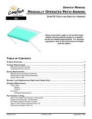
APPROXIMATE WEIGHT (LBS.)<br />
Awning Length Weight Dim B Awning Length Weight Dim B Awning Length Weight Dim B<br />
12 134 6.5in 15 160 11.25in 19 194 17in<br />
13 143 16 169 20 203<br />
14 152 17 177 21 211<br />
18 186 22 220<br />
A (Awning Length)<br />
5.57"<br />
Back Plate (Awning Case)<br />
1 1/4"<br />
3" (ref)<br />
Mounting Plate (ref)<br />
8"<br />
6 3/8"<br />
B<br />
Lateral Arm Mount (ref)<br />
Figure 1. General Description - Mirage Patio Awning.<br />
B<br />
<strong>MIRAGE</strong>007a<br />
052979-301r6 1
<strong>MIRAGE</strong> Service Manual <strong>Carefree</strong> <strong>of</strong> <strong>Colorado</strong><br />
CANOPY REPLACEMENT<br />
During the following instructions, use the manual override procedure on page 24 to open and close the awning.<br />
Case End Plate<br />
Phillips Head<br />
Outer Spring Arms<br />
Screw<br />
Idler (ref)<br />
Rubber Well<br />
Nut<br />
Canopy<br />
Firmly Tie<br />
Elbows Together<br />
DETAIL A<br />
Socket Head<br />
Screw (2)<br />
End Cap<br />
Lead Rail End Plate<br />
Lead Rail<br />
DETAIL B<br />
DETAIL C<br />
Mirage038<br />
1. Disconnect power to the awnings.<br />
2. Open the awning several inches to expose the arm elbows.<br />
3. (refer to Detail A) Using a minimum 1/2" rope, firmly tie the elbows <strong>of</strong> the outer spring arms together, do not<br />
use bungee cords. When tying the rope, use a non-slip knot such as a square knot or equivalent.<br />
CAUTION<br />
FAILURE TO SECURE THE LEAD RAIL AS DESCRIBED WILL ALLOW THE SPRING ARMS TO UNEXPECTANTLY<br />
EXTEND OUT POSSIBLY CAUSING PERSONAL INJURY AND DAMAGE TO THE AWNING.<br />
4. Remove the fabric retainer screws in the leading rail and set aside.<br />
5. (refer to Detail B) Remove the phillips head screw and rubber well nut from the top <strong>of</strong> the case and the<br />
(2) socket head screws that attach the end cap from the inside <strong>of</strong> the awning case.<br />
6. Use the manual override (refer to page 24) to unroll the canopy until the slot in the tube is aligned with<br />
the awning case opening.<br />
7. Remove the end plate from the lead rail assembly.<br />
8. Remove the end plate from the awning case.<br />
NOTE: It will be necessary to firmly support the roller tube and keep it from coming out <strong>of</strong> the<br />
case.<br />
9. (refer to Detail C) From the idler end <strong>of</strong> the rollbar, simultaneously slide the old canopy out <strong>of</strong> the roller<br />
tube and lead rail.<br />
10. Inspect the slots in the roller tube and lead rail. Clean and deburr as required. Lightly spraying the<br />
inside <strong>of</strong> the slot with a dry silicone lubricant will aid in sliding the new fabric in.<br />
11. Slide the new canopy into the lead rail and roller. Both edges must be done at the same time. Orient<br />
the fabric so that the large polycord goes into the lead rail, the smaller polycord goes into the roller<br />
tube. The hem should be on the down side.<br />
12. Center the canopy into the slots <strong>of</strong> the rollbar and lead rail.<br />
13. Remove any support material from the rollbar and install the case and lead rail end plates.<br />
14. Use the manual override to roll the canopy onto the rollbar, the material rolls under the roller tube. Ensure<br />
the fabric rolls evenly onto the rollbar without wrinkling or folding.<br />
15. Once the fabric is snugly rolled up, remove the rope used to tie the arms together.<br />
16. Restore power to the awning.<br />
17. Extend and retract the awning several times. This will allow the canopy to self-center.<br />
NOTE: It may be necessary to adjust the motor limits. Refer to page 25.<br />
18. Install the fabric retainer screws in the lead rail.<br />
19. Install the end cap.<br />
2 052979-301r6
<strong>Carefree</strong> <strong>of</strong> <strong>Colorado</strong> Service Manual <strong>MIRAGE</strong><br />
SPRING ARM REPLACEMENT<br />
CAUTION THE SPRING ARM IS UNDER TENSION TO OPEN. USE EXTREME CARE TO FIRMLY HOLD THE<br />
SPRING ARMS DURING ASSEMBLY AND DISASSEMBLY TO AVOID ANY SUDDEN OR UNEXPECTED MOVEMENT BY THE<br />
ARM. SERIOUS PERSONAL INJURY AND/OR PROPERTY DAMAGE COULD OCCUR.<br />
REPLACING THE ARM<br />
The following procedure requires two people.<br />
1. Open the awning to the maximum extension or as<br />
wide as possible. This is to minimize the spring<br />
tension in the arms during this procedure.<br />
2. Disconnect power to the awning.<br />
3. Use a scaffold, ladder or other means to firmly<br />
support the lead rail.<br />
4. For arms with the sensor cable mounted, carefully<br />
remove the sensor cable from the wire channel on<br />
top <strong>of</strong> the arm. Use care to not bend, break or<br />
compromise the cable.<br />
5. (refer to Detail A) At the lead rail, remove the M12-<br />
1.25 lock washer and nut from the arm and lead rail<br />
connector.<br />
6. Slightly loosen the 6mm adjustment screw. DO NOT<br />
loosen the outer set screw.<br />
7. Firmly grasp the spring arm and slide the lead rail<br />
arm knuckle out <strong>of</strong> the lead rail connector. Allow the<br />
arm to extend to its maximum length outside the<br />
lead rail. Have a second person hold or otherwise<br />
support the unattached end.<br />
8. (refer to Detail B) Inside the case, remove the M12-<br />
1.25 x 25 bolt and washer from the side <strong>of</strong> the arm<br />
support. Remove the M12-1.25 x 40 bolt, washer<br />
and saddle from the front <strong>of</strong> the support.<br />
9. Slightly loosen the 6mm locking screw.<br />
Case Arm Knuckle<br />
Arm Support<br />
M12-1.25 x 40<br />
Bolt & Washer<br />
Detail B (Case)<br />
M12-1.25 x 25<br />
Bolt & Washer<br />
6mm Locking Screw<br />
Saddle<br />
Mirage037<br />
10. Firmly grasp the spring arm and slide the case arm knuckle out <strong>of</strong> the arm support. Set the old arm aside.<br />
11. If the arm has wire channel mounted for the sensor cable, carefully remove the channel from the arm to<br />
reuse on the new arm.<br />
12. On the replacement arm assembly, remove the lead rail connector and arm support bracket from the<br />
arm knuckles.<br />
NOTE: The lead rail connector and arm support bracket are included in case there is damage to the<br />
existing brackets. If there is no damage, it is not necessary to replace them with the arm.<br />
13. If replacing the lead rail connector or case arm support, go to page 4 then return to step 14.<br />
14. Using two people firmly hold the new arm assembly and remove the shipping ties. Allow the arm to<br />
slowly open to its maximum extension.<br />
CAUTION<br />
WHEN THE ARM IS CLOSED, IT CAN OPEN WITH SIGNIFICANT FORCE. USE CARE WHEN OPENING THE ARM.<br />
Tip: Use a floor or ground cover and place one knuckle and arm half on the ground. Have one person<br />
firmly hold the arm half on the ground while the second person carefully opens the other arm half.<br />
A<br />
B<br />
Lead Rail Connector<br />
6mm Adjustment Screw<br />
M12-1.25<br />
Rail Knuckle<br />
Washer & Nut<br />
Detail A (Lead Rail)<br />
052979-301r6 3
<strong>MIRAGE</strong> Service Manual <strong>Carefree</strong> <strong>of</strong> <strong>Colorado</strong><br />
15. Lift the arm assembly into position.<br />
16. (refer to Detail B) Slide the case arm knuckle into the support inside the case and secure with 1 each<br />
M12-1.25 x 25 bolt and washer and 1 each M12-1.25 x 40 bolt, washer and saddle. Do not tighten at<br />
this time.<br />
17. (refer to Detail A) Insert the lead rail arm knuckle into the lead rail connector and secure with 1 each<br />
M12-1.25 bolt, washer and nut. Do not tighten at this time.<br />
18. If the sensor cable is routed on the replacement arm:<br />
a. Attach a piece <strong>of</strong> wire channel to the top <strong>of</strong> each section <strong>of</strong> the arm. If using new channel, cut<br />
each piece slightly shorter than the arm extrusion. Attach the channel using double sided tape.<br />
b. Route the cable through the wire channel. At the arm joints, arch the cable slightly to avoid<br />
binding. Do not twist the cable.<br />
Tip: Use a small tool, such as a flat bladed screwdriver to gently spread open the channel then insert<br />
the cable. Do this for the entire length <strong>of</strong> the channel until the cable is fully inserted.<br />
19. Adjust the arm pitch as required. Follow the procedure for pitch adjustment on page 24.<br />
20. Extend and retract the awning several times. This will allow the canopy to self-center.<br />
NOTE: It may be necessary to adjust the motor limits. Refer to page 25.<br />
To Replace the Lead Rail Connector:<br />
1. Remove the lead rail end plate.<br />
2. Carefully mark the location <strong>of</strong> the existing connector.<br />
3. Loosen the 6mm securing screw and slide the existing connector from the lead rail. This is the outer<br />
hex screw.<br />
4. Insert the new connector assembly into the lead rail and position at the marks made previously.<br />
5. Tighten the outer 6mm securing screw.<br />
6. Attach the lead rail end plate.<br />
To Replace the Case Arm Support<br />
1. Carefully mark the location <strong>of</strong> the existing support.<br />
2. Remove the end cap if installed.<br />
3. Remove the end plate.<br />
For the idler side, slide the end plate <strong>of</strong>f <strong>of</strong> the roller tube idler and set aside. (Refer to details on page 2.)<br />
For the motor side, Support the roller tube and carefully pull the motor and end plate out 3"-4".<br />
(Refer to details on page 5.)<br />
CAUTIONS<br />
WHEN PULLING THE MOTOR OUT OF THE CASE, THE SERVICING TECHNICIAN MUST USE CARE TO NOT<br />
BREAK OR DAMAGE THE MOTOR CABLES.<br />
WHEN PULLING THE MOTOR, DO NOT LET THE ROLLBAR COME OUT MORE THAN 1"; OTHERWISE THE<br />
ROLLBAR IDLER WILL DISENGAGE FROM THE OPPOSITE END PLATE. IF THIS OCCURS, REINSERT THE<br />
IDLER INTO THE ENDPLATE BEFORE CONTINUING (REFER TO ILLUSTRATION UNDER CANOPY<br />
REPLACEMENT ON PAGE 2 FOR IDLER DESCRIPTION).<br />
4. Loosen the clamping screws on the support and slide the old support out <strong>of</strong> the case.<br />
5. Insert the new support assembly into the case and position at the marks made previously.<br />
6. Tighten the clamping screws.<br />
7. For an idler side replacement. Reinstall the end plate. Ensure that the idler pin <strong>of</strong> the roller tube is<br />
properly seated.<br />
8. For a motor side replacement. Press the motor back into the rollbar. Ensure that the idler pin <strong>of</strong> the<br />
roller tube is properly seated on the opposite side. Reattach the end plate to the case.<br />
9. Reinstall the end caps if previously installed.<br />
10. Return to step 14 on the previous page.<br />
4 052979-301r6
<strong>Carefree</strong> <strong>of</strong> <strong>Colorado</strong> Service Manual <strong>MIRAGE</strong><br />
MOTOR REPLACEMENT<br />
During the following instructions, use the manual override procedure on page 24 to open and close the awning.<br />
Outer Spring Arms<br />
Firmly Tie<br />
Elbows Together<br />
DETAIL A<br />
Phillips Head<br />
Screw<br />
Rubber Well<br />
Nut<br />
Socket Head<br />
Screw (2)<br />
End Cap<br />
Roll Bar (ref)<br />
Drive Gear (ref)<br />
Motor<br />
Crown (ref)<br />
Case End Plate<br />
DETAIL B<br />
DETAIL C<br />
Mirage039<br />
1. Disconnect power to the awning.<br />
2. Open the awning several inches to expose the arm elbows.<br />
3. (refer to Detail A) Using a minimum 1/2" rope, firmly tie the elbows <strong>of</strong> the outer spring arms together, do not<br />
use bungee cords. When tying the rope, use a non-slip knot such as a square knot or equivalent.<br />
CAUTION<br />
FAILURE TO SECURE THE LEAD RAIL AS DESCRIBED WILL ALLOW THE SPRING ARMS TO UNEXPECTANTLY<br />
EXTEND OUT POSSIBLY CAUSING PERSONAL INJURY AND DAMAGE TO THE AWNING.<br />
4. (refer to Detail B) Remove the phillips head screw and rubber well nut from the top <strong>of</strong> the case and the<br />
(2) socket head screws that attach the end cap from the inside <strong>of</strong> the awning case.<br />
NOTE: It will be necessary to firmly support the roller tube to keep it from coming out <strong>of</strong> the<br />
case.<br />
5. (refer to Detail C) Remove the attaching screws then pull the end plate and motor partially out from the<br />
awning case.<br />
<br />
CAUTIONS<br />
WHEN PULLING THE MOTOR OUT OF THE CASE, THE SERVICING TECHNICIAN MUST USE CARE TO NOT<br />
BREAK OR DAMAGE THE MOTOR CABLES.<br />
WHEN PULLING THE MOTOR, DO NOT LET THE ROLLBAR COME OUT MORE THAN 1"; OTHERWISE THE<br />
ROLLBAR IDLER WILL DISENGAGE FROM THE OPPOSITE END PLATE. IF THIS OCCURS, REINSERT THE<br />
IDLER INTO THE ENDPLATE BEFORE CONTINUING (REFER TO ILLUSTRATION UNDER CANOPY<br />
REPLACEMENT ON PAGE 2 FOR IDLER DESCRIPTION).<br />
6. Disconnect the motor wires from inside the coach and pull out or clip the motor wires. If cutting the<br />
motor wires be sure to leave enough wire that can be stripped and spliced.<br />
7. Pull the motor out <strong>of</strong> the roller tube and remove the attaching screws holding the motor to the end plate.<br />
Make note <strong>of</strong> the motor orientation on the end plate. Do not discard the hardware.<br />
8. Remove the drive gear and crown from the old motor and install on the new motor.<br />
9. Attach the new motor to the end plate paying attention to match the orientation from the old motor.<br />
10. Slide the new motor assembly into the roller tube. Ensure that the motor drive gear and crown are<br />
properly seated inside the roller tube.<br />
11. Route the new motor wire into the coach and attach (refer to wiring diagrams on pages 15 - 19 for the<br />
appropriate control system) or if the wires were cut, splice the new wires to the existing wires. Ensure<br />
that the wire colors match (i.e. red to red and black to black). All wiring must conform to NEC<br />
(National Electrical Code) and local codes.<br />
12. Attach the end plate to the case.<br />
13. Remove the roller tube support.<br />
14. To test, restore power then extend and retract the awning.<br />
15. It will be necessary to adjust the motor limits. Refer to page 25.<br />
16. After completing the adjustments, install the end cap.<br />
052979-301r6 5
<strong>MIRAGE</strong> Service Manual <strong>Carefree</strong> <strong>of</strong> <strong>Colorado</strong><br />
HAND CRANK REPLACEMENT<br />
NOTE: Replacement crank assemblies have a shorter extension shaft. The eyelet does not extend<br />
below the case. If replacing an original crank, it is also necessary to replace the crank<br />
handle (crank handle p/n R001564).<br />
Spring Arms<br />
1/4-20 x 1 SHC Screw<br />
Spacer Attach (qty: 2)<br />
4.2 x 25mm PPH Screw<br />
Endplate Attach (qty: 3)<br />
6.1 x 50mm SHC Screw<br />
Crank Attach (qty: 2)<br />
#10 x 1 PTH Screw<br />
and Well Nut<br />
Firmly Tie<br />
Elbows Together<br />
DETAIL A<br />
#8 x 1 SHC Screw<br />
Spacer Endcap Attach (qty: 2)<br />
Crank DETAIL B<br />
Mirage050<br />
1. Open the awning 12" inches to expose the arm elbows.<br />
2. (refer to Detail A) Using a minimum 1/2" rope, firmly tie the elbows <strong>of</strong> the outer spring arms together, do not<br />
use bungee cords. When tying the rope, use a non-slip knot such as a square knot or equivalent.<br />
CAUTION<br />
FAILURE TO SECURE THE LEAD RAIL AS DESCRIBED WILL ALLOW THE SPRING ARMS TO UNEXPECTANTLY<br />
EXTEND OUT POSSIBLY CAUSING PERSONAL INJURY AND DAMAGE TO THE AWNING.<br />
3. (refer to Detail B) Remove the phillips head screw and rubber well nut from the top <strong>of</strong> the case and<br />
the (2) socket head screws that attach the end cap from the inside <strong>of</strong> the awning case.<br />
NOTE: It will be necessary to support the roller tube to keep it from coming out <strong>of</strong> the case. A rag<br />
can be stuffed between the tube and case to temporarily hold the roller tube in place.<br />
4. Remove the attaching screws then pull the end plate and hand crank out from the awning case and<br />
roller tube.<br />
CAUTION<br />
WHEN REMOVING THE CRANK, DO NOT LET THE ROLLER TUBE COME OUT MORE THAN 1"; OTHERWISE, THE<br />
ROLLBAR IDLER WILL DISENGAGE FROM THE OPPOSITE END PLATE. IF THIS OCCURS, REINSERT THE IDLER INTO<br />
THE ENDPLATE BEFORE CONTINUING (REFER TO ILLUSTRATION ON PAGE 2 FOR IDLER DESCRIPTION).<br />
5. Remove the screws holding the spacer to the end plate. Set parts aside and save.<br />
6. Remove the screws holding the crank to the spacer. Note the hole position and orientation <strong>of</strong> the<br />
parts. Set parts aside and save.<br />
7. Attach the new crank to the spacer using the screws removed previously.<br />
8. Attach the spacer to the end plate paying attention to match the orientation.<br />
9. Calibrate the hand crank.<br />
For LH cranks:<br />
a) Twist the eyelet clockwise until it stops.<br />
a)<br />
b) Twist the eyelet counterclockwise 4 turns plus (+) 4.5 turns for every 6" b)<br />
the awning was opened in step 1. (see sample below).<br />
Left Hand Crank<br />
For RH cranks:<br />
a) Twist the eyelet counterclockwise until it stops.<br />
b) Twist the eyelet clockwise 4 turns plus (+) 4.5 turns for every 6" the<br />
<br />
awning was opened in step 1. (see sample below).<br />
a)<br />
Sample <strong>of</strong> calculating turns: If awning was opened 12" in step one then the<br />
b)<br />
number <strong>of</strong> turns would be 4 + (2 x 4.5) = 13.<br />
10. Attach the end plate to the case.<br />
11. Remove the roller tube support.<br />
12. Install the end cap.<br />
Right Hand Crank<br />
Mirage051<br />
6 052979-301r6
<strong>Carefree</strong> <strong>of</strong> <strong>Colorado</strong> Service Manual <strong>MIRAGE</strong><br />
DIAGNOSTICS/TROUBLESHOOTING<br />
The following procedures are intended to aid the service technician to logically resolve operational issues with the<br />
Mirage installation. These procedures do not address conditions that may arise with the basic awning installation.<br />
When procedures are system specific, the four electrical systems are designated as:<br />
System #1, Direct Connect (No Relay Box) Reference Wiring Diagram - page 15<br />
System #2, Switches w/ Relay Control Box Reference Wiring Diagram - page 16<br />
System #3, Standard Electronics w/ Optional Auto-Retract Reference Wiring Diagram - page 18<br />
System #4, Direct Response Electronics Reference Wiring Diagram - page 19<br />
System #4, Direct Response Electronics, Winnebago Reference Wiring Diagram - page 20<br />
Common Operation Items<br />
1. For Direct Response: If the optional ignition lockout is installed, the system will disable the extend function<br />
while the vehicle ignition key is in the ON position. Operation will return to normal when the key is OFF.<br />
WARNING<br />
ALWAYS DISCONNECT POWER WHEN CONNECTING OR DISCONNECTING 110VAC WIRES.<br />
Procedures in this section:<br />
Page<br />
COMMON OPERATION ITEMS ..................................................................................................................... 7<br />
SYSTEM TESTS ........................................................................................................................................ 8<br />
STANDARD ELECTRONICS W/ OPTIONAL AUTO-RETRACT ............................................................... 8<br />
TESTING THE REMOTE ................................................................................................................... 8<br />
DIRECT RESPONSE ....................................................................................................................... 8<br />
TESTING THE KEY FOB ................................................................................................................. 9<br />
D01 THE AWNING DOES NOT OPERATE .......................................................................................... 10<br />
D02 THE AWNING OPERATES DIFFERENTLY THAN THE SWITCH MARKINGS ...................................... 11<br />
D03A AWNING DOES NOT AUTO-RETRACT IN WIND (STANDARD ELECTRONICS) ................................. 12<br />
D03B AWNING DOES NOT AUTO-RETRACT IN WIND (DIRECT RESPONSE) ........................................... 12<br />
D04A REMOTE DOES NOT OPERATE (STANDARD ELECTRONICS W/ OPTIONAL REMOTE) .................... 13<br />
D04B REMOTE DOES NOT OPERATE (DIRECT RESPONSE) ................................................................ 13<br />
052979-301r6 7
<strong>MIRAGE</strong> Service Manual <strong>Carefree</strong> <strong>of</strong> <strong>Colorado</strong><br />
SYSTEM TESTS<br />
Standard Electronics w/ Optional Auto-Retract<br />
1. Provide 110VAC and 12DC power to the awning system.<br />
2. At the switch panel, turn the POWER SWITCH to "ON".<br />
3. Press the button to extend the awning. The awning will continue to the maximum extension.<br />
4. Pressing the button again will stop the awning.<br />
5. Press the button a third time and the awning will retract.<br />
6. Set the WIND SPEED switch to 12 mph. Refer to Setting the Wind Speed Sensitivity on page 26.<br />
7. Extend the awning using the PATIO switch.<br />
8. Spin the anemometer. The awning should retract automatically to the closed position.<br />
NOTE: Do not hit the anemometer to spin. Using compressed air provides a constant pressure<br />
source and the output can be regulated to test the various sensitivity settings. DO NOT<br />
position the nozzle closer than 10 inches from the cups.<br />
9. Repeat steps 7 and 8 two (2) more times with the Wind Speed switch set to a medium value and then<br />
to higher value.<br />
10. Repeat steps 7 through 8 with the Power switch set to OFF. The awning should not move.<br />
If the awning does not operate as described:<br />
If the awning extends, reverse the red and black motor wires. Refer to the wiring diagram.<br />
<br />
<br />
If the awning does not stop at maximum extend or retract, it may be necessary to adjust the "in" and/or<br />
"out" limit switches. Refer to page 25.<br />
If the awning does not operate, check the wiring and power according to the wiring diagram.<br />
TESTING THE REMOTE<br />
1. Turn the power switch to "ON".<br />
2. On the remote, press and release the down arrow. The awning should extend.<br />
3. Press and release the stop (center) button. The awning should stop.<br />
4. Press and release the up arrow. The awning should retract and stop automatically when fully closed.<br />
If the awning does not operate as described:<br />
If the awning moves in a direction opposite than described; in the control box, reverse the red and black<br />
wires from the motor.<br />
If the awning does not operate using the remote; program the remote following the directions on page 26.<br />
Direct Response w/ DKS Style Switch Panel<br />
When 110VAC power is removed from the system, the controller DOES NOT retain previous positioning<br />
information. When power is restored, positioning information is updated when the first function is initiated.<br />
The function LEDs (extend, retract and stop) perform a dual function. When the button is pressed, the LED<br />
illuminates. The LED stays illuminated during the selected operation and after the awning has fully extended or<br />
retracted. This provides an indicator <strong>of</strong> the awning position. When the stop button is pressed, the LED will<br />
illuminate and stay on until a function is pressed. If on, it indicates that the awning is partially extended/retracted.<br />
All function buttons are press ON/press OFF. The auto-functions will continue until the awning is fully<br />
extended/retracted or when the stop button is pressed.<br />
8 052979-301r6
<strong>Carefree</strong> <strong>of</strong> <strong>Colorado</strong> Service Manual <strong>MIRAGE</strong><br />
1. While observing the control panel, have a second person initiate 110VAC power to the coach and<br />
awning system. The following should occur:<br />
1.1 The Auto-Retract and Wind Speed LEDs should illuminate briefly then extinguish.<br />
1.2 The Power ON/OFF and function/position LEDs will briefly illuminate.<br />
1.3 The system then goes to the default settings: The POWER “ON”, AUTO-RETRact “ON” and MEDIUM<br />
Wind Speed LED will be on.<br />
NOTE: The function/position LEDs (extend, stop and retract) will not be illuminated. During<br />
power up the controller does not retain position information. The controller is<br />
updated with the first function used.<br />
2. Press the POWER “OFF”. ALL LEDs should extinguish. The POWER ON/OFF button disables all functions<br />
including Auto-Retract and the optional RF remote if installed. It does not disconnect the 110VAC power.<br />
3. Press the POWER “ON”. Press the EXTEND button, the LED should illuminate while the awning extends and<br />
stay on after the awning auto-stops. Observe the awning, it should fully extend. The system performs an<br />
auto-tension action when the awning is fully extended. The awning rolls in reverse to tension the fabric. The<br />
auto-tension feature works only with the extend function when the awning is fully extended or the stop button<br />
is pushed while extending.<br />
4. After the awning is fully extended, press the RETRACT button, the EXTEND LED should extinguish and<br />
the Retract LED should illuminate while the awning is retracting. Press the STOP button.<br />
5. When the STOP button is pressed, the awning will stop, the RETRACT LED should extinguish and the<br />
STOP LED should illuminate.<br />
6. Press the RETRACT button, allow the awning to retract fully, the Retract LED will illuminate and stay lit.<br />
7. Press the AUTO-RETRACT OFF. The AUTO-RETRACT and WIND SPEED LEDs should go out.<br />
8. Press the AUTO-RETRACT ON. Press each Wind Speed button and confirm that the LEDs illuminate.<br />
9. Test the Auto-Retract function:<br />
9.1 Fully extend the awning.<br />
9.2 With the AUTO-RETRACT ON, set the WIND SPEED to the lowest setting.<br />
9.3 Create a firm but gentle rocking motion with the leading edge <strong>of</strong> the awning. The awning should retract<br />
after 2-3 seconds <strong>of</strong> the motion.<br />
10. If the optional Ignition Sensor is installed:<br />
10.1 Partially retract the awning.<br />
10.2 Turn the ignition key ON.<br />
10.3 Press the EXTEND button. The LED should flash for 2 seconds then shut <strong>of</strong>f and the previous<br />
function LED will come back on.<br />
Testing the Key FOB<br />
1. Ensure that the system is OFF at the switch panel.<br />
2. Press each button on the Key FOB. The awning should not move.<br />
3. Turn the system on.<br />
4. Press and release the EXTEND button. The awning should extend automatically.<br />
5. Press and release the RETRACT button on the Key FOB. The awning should retract automatically.<br />
6. While the awning is retracting, press and release the STOP button on the Key FOB. The awning<br />
should stop when the button is pushed.<br />
052979-301r6 9
<strong>MIRAGE</strong> Service Manual <strong>Carefree</strong> <strong>of</strong> <strong>Colorado</strong><br />
In the charts below, YES is a positive response to the test; NO is a negative response.<br />
D01 THE AWNING DOES NOT OPERATE<br />
A Confirm 110VAC power to control box.<br />
1. Shut <strong>of</strong>f power source.<br />
2. Open control box.<br />
3. On some early units a fuse is installed on the circuit<br />
board (if installed). Check that fuses on circuit boards<br />
are intact.<br />
4. Check that 110VAC connections are correct and secure.<br />
Refer to correct system schematic.<br />
B Confirm awning motor is functioning<br />
1 1.1 With power <strong>of</strong>f, disconnect motor wires and AC<br />
power in from switches (system #1) or control box.<br />
1.2 Connect awning motor directly to 110VAC power<br />
source.<br />
Motor White to Neutral (White) <strong>of</strong> AC cord<br />
Motor Green to Ground (Green) <strong>of</strong> AC cord<br />
Motor Red & Black are Motor Direction Control –<br />
connect Red to AC Hot (Black).<br />
1.3 While observing awning, briefly apply power.<br />
1.4 Disconnect power and attach other motor direction<br />
control wire (Black) to AC Hot (Black).<br />
1.5 While observing awning, briefly apply power.<br />
1.6 Does awning move when power is applied<br />
Note: If the awning runs but does not extend or retract<br />
completely, it may be necessary to adjust the motor<br />
limits (refer to page 25).<br />
C<br />
2 Test continuity and connections <strong>of</strong> motor wire between<br />
control box and junction box.<br />
Test Control Switches (Systems #1, 2, 3 Only)<br />
This test requires the use <strong>of</strong> a continuity tester.<br />
1. Disconnect wires from switch to be tested.<br />
2. Attach the first probe to the common (center) terminal; attach<br />
the second probe to the second terminal.<br />
3. With switch in neutral or <strong>of</strong>f position, does meter indicate an<br />
open circuit<br />
4. Activate switch, does meter indicate a closed circuit<br />
5. For double direction switches, move the second probe to the<br />
third terminal and repeat step 4.<br />
YES<br />
NO<br />
Power is present; go to test B<br />
Check vehicle circuits and fuses.<br />
Repair as required and retest<br />
YES Awning motor is good, control circuit<br />
is defective – test and repair<br />
For System #1, 2, 3 – Go to Step C<br />
For System #4 – Go to Step D<br />
NO Go to step B-2<br />
YES<br />
NO<br />
Continuity is good, motor is<br />
defective – replace<br />
Repair wire as required and retest<br />
YES Switches are good, control box is<br />
defective – replace<br />
NOTE: Relay box for system #2<br />
is no longer available. It will be<br />
necessary to replace with system<br />
#3 control box and switches.<br />
Follow the diagram on page 18.<br />
NO If answer to any <strong>of</strong> question (3 – 5)<br />
is no, switch is defective – replace.<br />
D01 Continued on next page<br />
10 052979-301r6
<strong>Carefree</strong> <strong>of</strong> <strong>Colorado</strong> Service Manual <strong>MIRAGE</strong><br />
D01 THE AWNING DOES NOT OPERATE<br />
(continued from previous page)<br />
D Test Key pad (System #4 – Direct Response Only)<br />
1 Confirm 110VAC power to control box<br />
1.1 Shut <strong>of</strong>f power source.<br />
1.2 Open control box.<br />
1.3 On some early units a fuse is installed on the circuit<br />
board. Check that fuses on circuit boards are<br />
intact.<br />
1.4 Check that 110VAC connections and splices to<br />
board is correct and secure. Refer to system<br />
schematic.<br />
1.5 While observing the circuit boards, have power<br />
restored. The LEDs on the boards should blink red<br />
then green.<br />
2 Press the "Power On" button on the touch-pad. The<br />
"Power On" LED should illuminate.<br />
3 Check the cable between the switch and control box.<br />
As a continuity check, Pin 1 <strong>of</strong> connector 1 goes to Pin<br />
1 <strong>of</strong> connector 2; pin 2 goes to pin 2; pin 3 goes to pin 3<br />
and pin 4 goes to pin 4.<br />
4 Check the function <strong>of</strong> the Key pad<br />
4.1 On the control board, locate the terminal strip next<br />
to the phone cord connectors.<br />
4.2 Insert 3 wires into the terminals shown below<br />
4.3 While observing the awning, short the wire ends<br />
between the Common and Extend terminals.<br />
Does the awning move<br />
4.4 Short the wire ends between the Common and<br />
Retract terminals. Does the awning move<br />
YES<br />
NO<br />
Power is present; go to test B<br />
Check vehicle circuits and fuses.<br />
Repair as required and retest<br />
YES Power is on, go to step D-4<br />
NO LED does not illuminate, go to step<br />
D-3<br />
YES Continuity OK; go to step D-4<br />
NO Replace cable and retest<br />
YES<br />
NO<br />
Control Board is good, Key pad is<br />
defective - replace<br />
Control Board is defective – replace<br />
control box.<br />
Retract<br />
Extend<br />
Common<br />
<strong>MIRAGE</strong>040<br />
D02 THE AWNING OPERATES DIFFERENTLY THAN THE SWITCH MARKINGS<br />
This condition generally occurs during new installations or when major components have been replaced.<br />
A Does Awning operate in reverse <strong>of</strong> the switch plate labeling YES Motor wires from awning are<br />
(i.e. extends when retract is pushed)<br />
reversed - locate motor wires in the<br />
control box, reverse the red and<br />
black wires.<br />
052979-301r6 11
<strong>MIRAGE</strong> Service Manual <strong>Carefree</strong> <strong>of</strong> <strong>Colorado</strong><br />
D03A AWNING DOES NOT AUTO-RETRACT IN WIND (STANDARD ELECTRONICS)<br />
NOTE: For standard electronics with the optional auto-retract anemometer; the auto-retract system is always on.<br />
Confirm that the sensitivity is set correctly (if set on highest level, system may appear not to function). Setting the<br />
sensitivity is in the Owner's manual and on page 26.<br />
A<br />
B<br />
Confirm that the retract function works using the PATIO<br />
switch<br />
YES<br />
NO<br />
Function works using the switch; go to<br />
test B<br />
Function does not work with switch; go<br />
to procedure D01<br />
Test Anemometer<br />
1 Do the anemometer cups spin freely YES Go to step B2<br />
NO Anemometer defective - replace<br />
2 Test signal from anemometer:<br />
YES Control Box is defective - replace<br />
2.1 Remove anemometer wires from control box;<br />
NO The circuit stays open or stays closed;<br />
2.2 Place continuity tester between anemometer<br />
go to step B3<br />
wires;<br />
2.3 Have a helper slowly turn the anemometer:<br />
Does the circuit open and close It should open<br />
and close once for every revolution.<br />
3 Test the wire continuity between the control box and the YES Continuity OK; replace anemometer<br />
anemometer.<br />
NO Repair or Replace wires as required<br />
D03B AWNING DOES NOT AUTO-RETRACT IN WIND (DIRECT RESPONSE)<br />
A<br />
Press the power on button then press the auto-retract button.<br />
Does the auto-retract LED flash<br />
YES<br />
NO<br />
The flashing LED indicates that the<br />
sensor has been disengaged or<br />
otherwise disabled. Go to step C.<br />
Function does not work with switch;<br />
go to procedure D01<br />
B Confirm that the retract function works using the push buttons. YES Function works using the switch; go<br />
to test C<br />
NO Function does not work with switch;<br />
go to procedure D01<br />
C Test Motion Sensor<br />
1 Confirm cable is plugged into connector on box marked YES Go to step 2<br />
“Shaker”<br />
NO Correct as required and test.<br />
2 2.1 Unplug sensor from control box.<br />
2.2 Connect a second sensor into control box.<br />
2.3 Set the control switches for the auto retract function<br />
2.4 Hold the second sensor horizontally and gently move<br />
up and down.<br />
YES<br />
NO<br />
Awning retracts; original sensor<br />
defective - replace<br />
Awning does not retract; control box<br />
defective - replace<br />
12 052979-301r6
<strong>Carefree</strong> <strong>of</strong> <strong>Colorado</strong> Service Manual <strong>MIRAGE</strong><br />
D04A REMOTE DOES NOT OPERATE (STANDARD ELECTRONICS W/ OPTIONAL REMOTE)<br />
1 Confirm normal operation with switches If system does not operate, go to test<br />
D01<br />
2 Confirm batteries in remote are good. Pressing any<br />
Replace as needed<br />
button on the remote will illuminate the LED indicator on<br />
the remote<br />
4 Confirm that the receiver is programmed for the remote -- Refer to “Programming the remote on<br />
page 26 and retest. If system does<br />
not work; go to step 4<br />
5 Program a second remote and test YES 2 nd remote works. 1 st remote is<br />
defective.<br />
NO 2 nd remote does not work; control box<br />
receiver is defective - replace<br />
D04B REMOTE DOES NOT OPERATE (DIRECT RESPONSE)<br />
1 Confirm normal operation with touch pad If system does not operate, go to test<br />
D01<br />
2 Check the cable between the RR24 and control box. As a<br />
continuity check, Pin 1 <strong>of</strong> connector 1 goes to Pin 1 <strong>of</strong><br />
connector 2; pin 2 goes to pin 2; pin 3 goes to pin 3 and pin 4<br />
goes to pin 4.<br />
YES<br />
NO<br />
Cable is OK. Confirm that cable is<br />
securely plugged in; go to step 4<br />
Repair or Replace cable as required.<br />
Cable must be plugged into the "BUS" port <strong>of</strong> controller #1.<br />
3 Confirm that the RR24 is programmed for the Remote -- Refer to “Programming the Receiver”<br />
on page 27 and retest. If system<br />
does not work; go to step 5<br />
4 Program a second remote and test YES 2 nd Key FOB works. Replace battery<br />
in 1 st Key FOB and retest, if no<br />
response, 1 st Key FOB is defective.<br />
NO 2 nd remote does not work; go to step 6<br />
5 Replace the Receiver and test.<br />
YES System works OK. 1 st receiver is<br />
(it will be necessary to program receiver for remote)<br />
defective<br />
NO System does not work. Reinstall 1 st<br />
receiver; go to step 7<br />
6 Replace control box --<br />
052979-301r6 13
<strong>MIRAGE</strong> Service Manual <strong>Carefree</strong> <strong>of</strong> <strong>Colorado</strong><br />
ELECTRICAL<br />
IMPORTANT NOTICES:<br />
Failure to follow the wiring instructions in this publication may void the motor warranty.<br />
All wiring must conform to NEC (National Electrical Code) and local codes.<br />
DO NOT wire two or more motors to one switch—No parallel wiring.<br />
<br />
The SO cable from the 110VAC awning motor can only pass directly through a wall, it can not be<br />
laid up in the wall and must be connected to NM wire or individual wires in conduit no more than<br />
6 inches past the point <strong>of</strong> entry.<br />
For 110VAC installations, enclosed junction boxes are required for all wire splices and direct<br />
connection switch installations. Boxes are required in conformance with prevailing<br />
construction codes. The servicing technician or installer is required to furnish the flush<br />
mounted, UL approved electrical duplex boxes where required.<br />
The 110V electronic control system provides the user with simple pushbutton controls for the awnings<br />
installed. Four configurations are available:<br />
WARNING<br />
ALWAYS DISCONNECT THE VEHICLE BATTERY AND ELECTRICAL SOURCES BEFORE WORKING WITH ELECTRICAL<br />
WIRING AND COMPONENTS.<br />
1) Direct Connect (reference as system #1). 110VAC is routed directly through the switches to the awning<br />
motor.<br />
System includes: 1 power switch and 1 patio (extend/retract) switch.<br />
This system is no longer <strong>of</strong>fered.<br />
2) Optional Relay Box (reference as system #2). 110VAC power is controlled by a relay control box. The<br />
switches use a 12VDC signal to control the relays. Switch installation is simplified; the switches do not<br />
require a duplex box.<br />
System includes: 1 power switch, 1 patio (extend/retract) switch and 1 relay control box.<br />
This system is no longer <strong>of</strong>fered.<br />
3) Standard Electronics w/ Optional Auto-Retract (reference as system #3). The optional auto-retract<br />
system detects adverse wind conditions and retracts the awning. Sensitivity is set by the user.<br />
Standard system includes: 1 power switch, 1 patio (extend/retract) switch, 1 control box<br />
An optional anemometer is available for the auto-retract system; and<br />
An optional remote control is available.<br />
4) Direct Response (reference as system #4). The 110V electronic control system provides the user with<br />
simple pushbutton controls for the awning. The Direct Response electronic system is a premier autoretract<br />
system that detects motion from adverse wind conditions and retracts the awning. Sensitivity<br />
is set by the user<br />
System includes: Control box, Master control panel (w/ pushbutton awning control and windspeed<br />
sensitivity setting), motion sensor.<br />
An optional RF remote control is available with the Direct Response system.<br />
An optional ignition lockout is available.<br />
The switches use a 5VDC signal to operate the control box; thus eliminating the need for a junction<br />
box for the control panel.<br />
Components are connected using terminated cables. Terminated cable is 4-wire RJ11 terminated<br />
phone cord (straight, no twist). This does not include 110VAC power in or awning motor power.<br />
14 052979-301r6
<strong>Carefree</strong> <strong>of</strong> <strong>Colorado</strong> Service Manual <strong>MIRAGE</strong><br />
WIRING HARNESS – OPTIONAL LIGHT & SPEAKER END CAPS<br />
(THIS SYSTEM IS NO LONGER AVAILABLE)<br />
+12VDC<br />
Stereo<br />
Consult Stereo Manual<br />
for Speaker Connections<br />
Shielded Outdoor Speaker Grade Wire<br />
16 AWG UL Listed<br />
Outdoor Grade Wire 16 AWG UL Listed<br />
Idler Side<br />
Motor Side<br />
Mirage041<br />
WIRING DIAGRAM - DIRECT CONNECT (NO RELAY CONTROL BOX)<br />
SYSTEM #1 (THIS SYSTEM IS NO LONGER AVAILABLE)<br />
To 110VAC<br />
2 Conductor<br />
14AWG NM Wire<br />
w/ Ground<br />
Green<br />
White<br />
Black<br />
1<br />
3<br />
5<br />
7<br />
Power<br />
Switch<br />
2<br />
4<br />
6<br />
8<br />
1<br />
3<br />
5<br />
7<br />
Patio<br />
Switch<br />
Green<br />
White<br />
Black<br />
Red<br />
2<br />
4<br />
6<br />
8<br />
3 Conductor<br />
14AWG NM Wire<br />
w/ Ground<br />
UL Approved Junction Box<br />
Install per Construction Code<br />
Installer Furnished<br />
A<br />
Green<br />
White<br />
Black<br />
Red<br />
Red<br />
Black<br />
1<br />
3<br />
5<br />
7<br />
From<br />
Motor<br />
2<br />
4<br />
6<br />
8<br />
Patio<br />
Switch<br />
Detail A<br />
For LH Configuration<br />
Reverse Red & Black Wires<br />
on Switch Terminals 1 & 7<br />
<strong>MIRAGE</strong>015<br />
052979-301r6 15
<strong>MIRAGE</strong> Service Manual <strong>Carefree</strong> <strong>of</strong> <strong>Colorado</strong><br />
WIRING DIAGRAM –SWITCHES W/ RELAY CONTROL BOX - PREVIOUS<br />
SYSTEM #2 - The current configuration <strong>of</strong> this switch configuration has been updated to use<br />
R019468-006 switch kit. For switch replacement use R019468-006 kit and the wiring diagram on the<br />
next page.<br />
1<br />
3<br />
5<br />
7<br />
Power<br />
Switch<br />
2<br />
4<br />
6<br />
8<br />
1<br />
3<br />
5<br />
7<br />
2<br />
4<br />
6<br />
8<br />
Patio<br />
Switch<br />
1 2 3 4 5 6 7 8 9 10<br />
+12VDC<br />
A<br />
Black<br />
Red<br />
Detail A<br />
For LH Configuration<br />
Reverse Red & Black Wires<br />
on T erminals 4 & 5<br />
1 2<br />
3<br />
4<br />
5<br />
6<br />
7<br />
8<br />
9 10<br />
From<br />
Motor<br />
Red<br />
Black<br />
Green<br />
White<br />
12VDC<br />
Ground<br />
Red<br />
Black<br />
Green<br />
White<br />
3 Conductor<br />
14AWG NM Wire<br />
w/ Ground<br />
Black<br />
White<br />
Ground<br />
T o<br />
110 V A C<br />
2 Conductor<br />
14 A WG NM Wir e<br />
w/ Ground<br />
<strong>MIRAGE</strong>016<br />
FROM TO (RH CONFIGURATION) TO (LH CONFIGURATION)<br />
Patio Switch Terminal 1 Control Box Terminal 1 Control Box Terminal 1<br />
Terminal 7 Terminal 2 Terminal 2<br />
Power Switch Terminal 6 Patio Switch Terminal 3 Patio Switch Terminal 3<br />
Terminal 8 12VDC Power Source 12VDC Power Source<br />
Motor Red Control Box Terminal 4 Control Box Terminal 5<br />
Black Terminal 5 Terminal 4<br />
Ground Terminal 6 Terminal 6<br />
White Terminal 8 Terminal 8<br />
AC Power<br />
Source<br />
Ground Control Box Terminal 7 Control Box Terminal 7<br />
White Terminal 9 Terminal 9<br />
Black Terminal 10 Terminal 10<br />
16 052979-301r6
<strong>Carefree</strong> <strong>of</strong> <strong>Colorado</strong> Service Manual <strong>MIRAGE</strong><br />
WIRING DIAGRAM –SWITCHES W/ RELAY CONTROL BOX - CURRENT<br />
SYSTEM #2<br />
+12VDC<br />
Extend/Retract<br />
Rear View<br />
<strong>of</strong> Switch<br />
On/Off<br />
1 2 3 4 5 6 7 8 9 10<br />
Black<br />
Red<br />
A<br />
Detail A<br />
For LH Configuration<br />
Reverse Red & Black Wires<br />
on Terminals 4 & 5<br />
1 2<br />
3<br />
4<br />
5<br />
6<br />
7<br />
8<br />
9 10<br />
From<br />
Motor<br />
Red<br />
Black<br />
Green<br />
White<br />
12VDC<br />
Ground<br />
Red<br />
Black<br />
Green<br />
White<br />
3 Conductor<br />
14AWG NM Wire<br />
w/ Ground<br />
Black<br />
White<br />
Ground<br />
To<br />
110VAC<br />
2 Conductor<br />
14AWG NM Wire<br />
w/ Ground<br />
<strong>MIRAGE</strong>016a<br />
FROM TO (RH CONFIGURATION) TO (LH CONFIGURATION)<br />
Extend/Retract Upper Terminal<br />
Terminal 1<br />
Terminal 1<br />
Control Box<br />
Control Box<br />
Switch<br />
Lower Terminal Terminal 2 Terminal 2<br />
ON/OFF Switch 1st Terminal 1 Extend/Retract<br />
Extend/Retract<br />
Center Terminal<br />
Switch<br />
Switch<br />
Center Terminal<br />
2nd Terminal 1 12VDC Power Source 12VDC Power Source<br />
Red<br />
Terminal 4<br />
Terminal 5<br />
Motor<br />
Black Terminal 5 Terminal 4<br />
Control Box<br />
Control Box<br />
Ground Terminal 6 Terminal 6<br />
White Terminal 8 Terminal 8<br />
Ground<br />
Terminal 7<br />
Terminal 7<br />
AC Power<br />
White Control Box Terminal 9 Control Box Terminal 9<br />
Source<br />
Black Terminal 10 Terminal 10<br />
NOTES:<br />
1. Wires to ON/OFF Switch are not pin specific.<br />
2. The SO cable from the 110VAC awning motor can only pass directly through a wall, it can not be laid up in the<br />
wall and must be connected to NM wire or individual wires in conduit no more than 6 inches past the point <strong>of</strong><br />
entry.<br />
052979-301r6 17
<strong>MIRAGE</strong> Service Manual <strong>Carefree</strong> <strong>of</strong> <strong>Colorado</strong><br />
WIRING DIAGRAM – STANDARD ELECTRONICS W/ OPTIONAL AUTO RETRACT<br />
SYSTEM #3 (THIS SYSTEM IS NO LONGER AVAILABLE)<br />
A<br />
+12VDC<br />
GND<br />
UP<br />
DOWN<br />
COM<br />
NEUT<br />
HOT<br />
Green<br />
Red<br />
Black<br />
White<br />
WIND<br />
COMMON<br />
3 Conductor<br />
14AWG NM Wire<br />
w/ Ground<br />
Green<br />
Red<br />
Black<br />
White<br />
Installer Furnished<br />
Junction Box<br />
From<br />
Motor<br />
Black<br />
Green<br />
To110 VAC<br />
White<br />
2 Conductor<br />
14AWG NM Wire<br />
w/ Ground<br />
Wires for Patio Switch<br />
are not pin specific<br />
Wires for Anemometer<br />
are not pin specific<br />
Anemometer<br />
12VDC<br />
Ground<br />
1<br />
3<br />
5<br />
7<br />
Power<br />
Switch<br />
2<br />
4<br />
6<br />
8<br />
Patio<br />
Switch<br />
GND<br />
UP<br />
DOWN<br />
COM<br />
NEUT<br />
HOT<br />
Green<br />
Black<br />
Red<br />
White<br />
Detail A<br />
For RH motor configurations:<br />
Red Motor Wire goes to “DOWN” Terminal<br />
Black Motor Wire goes to “UP” Terminal<br />
Mirage031<br />
18 052979-301r6
Power<br />
On/Off<br />
Extend<br />
Stop<br />
Retract<br />
Auto-Retract<br />
On/Off<br />
Wind Speed<br />
High<br />
Low<br />
<strong>Carefree</strong> <strong>of</strong> <strong>Colorado</strong> Service Manual <strong>MIRAGE</strong><br />
WIRING DIAGRAM – DIRECT RESPONSE ELECTRONICS<br />
3 Conductor 14AWG<br />
NM Wire w/ Gnd<br />
3<br />
RED<br />
BLK<br />
WHT<br />
GRN<br />
RH Motor Wire Shown<br />
See Detail A for LH Motor<br />
AMD<br />
Awning #1<br />
Sensor<br />
Sensor<br />
5<br />
Ignition Switched<br />
+12VDC<br />
12VDC<br />
Ground<br />
Splitter<br />
4<br />
Ignition<br />
Lockout<br />
Sensor<br />
(Optional)<br />
TO<br />
EYE PORT<br />
on RP24<br />
Program<br />
Mode<br />
Press to Learn<br />
Transmitter<br />
RF<br />
Receiver<br />
UP<br />
2 Conductor 14AWG<br />
NM Wire w/ Gnd<br />
To 110VAC<br />
wht<br />
blk<br />
grn<br />
NOTES:<br />
1 Wire Legend:<br />
RED<br />
BLK<br />
WHT<br />
GRN<br />
1<br />
2<br />
3<br />
4<br />
5<br />
6<br />
7<br />
AUX SUN<br />
EYE<br />
DSK<br />
Red<br />
Black<br />
White<br />
Green (Ground)<br />
Remote<br />
Key Pad<br />
2 For RH Motor Configurations: Motor Red goes to Pin (1); Motor Black goes to Pin (2)<br />
For LH Motor Configurations: Motor Red goes to Pin (2) Black; Motor Black goes to pin (1)<br />
3 The SO cable from the 110VAC awning motor can only pass through a wall, it cannot be laid up in the wall<br />
and must be connected to NM wire or individual wires in conduit no more than 6 inches past the point <strong>of</strong> entry.<br />
4 Splitter is used only when Optional Lock-Out Sensor is installed. Connect RF Receiver directly to “EYE”<br />
if Lock-Out is not installed.<br />
5 Wires for the Ignition Lock-Out Sensor are not pin specific.<br />
6<br />
6<br />
wht<br />
blk<br />
grn<br />
BLK<br />
RED<br />
WHT<br />
GRN<br />
1<br />
2<br />
3<br />
4<br />
5<br />
6<br />
7<br />
Detail A<br />
For LH Configuration<br />
Reverse Red & Black Wires<br />
For early units: Label “DSK” was “ACC”; Label “EYE” was “BUS”; Label “AMD” was ”SHAKE”<br />
Ribbon<br />
Cable<br />
Wind Speed<br />
Rear View<br />
Switch Panel<br />
Detail B<br />
Used thru 2006<br />
Figure 2. Wiring Diagram – Direct Response System.<br />
FROM TO (RH CONFIGURATION) TO (LH CONFIGURATION)<br />
Motor Red Control Box 1 Control Box 2<br />
Black 2 1<br />
White 3 3<br />
Ground 6 6<br />
AC Power<br />
Source<br />
White Control Box 4 Control Box 4<br />
Black 5 5<br />
Ground 7 7<br />
Awning Sensor 10’ Cable Control Box “AMD” Control Box “AMD”<br />
Switch Assy 60“ Cable Control Box “DSK” Control Box “DSK”<br />
Splitter 60" Cable Control Box "EYE" Control Box "EYE"<br />
Receiver 60” Cable Splitter Splitter<br />
Ignition Lockout 60“ Cable Splitter Splitter<br />
Notes: 1. Cable lengths are the lengths <strong>of</strong> the furnished cables. If a connection requires a length greater than the supplied cable, the<br />
installer must provide a terminated jumper cable from the box location to the cable end.<br />
Patio<br />
DR012a<br />
052979-301r6 19
<strong>MIRAGE</strong> Service Manual <strong>Carefree</strong> <strong>of</strong> <strong>Colorado</strong><br />
WIRING DIAGRAM – DIRECT RESPONSE WINNEBAGO<br />
Ignition Switched<br />
+12VDC<br />
12VDC<br />
Ground<br />
OEM Lockout<br />
Harness<br />
Wires to Ignition Lockout<br />
are not pin specific<br />
RF<br />
Receiver<br />
Keypad<br />
Awning<br />
Sensor<br />
Ignition<br />
Lockout<br />
Sensor<br />
TO<br />
EYE PORT<br />
on RP24<br />
Program<br />
Mode<br />
Press to Learn<br />
Transmitter<br />
UP<br />
RED<br />
BLK<br />
WHT<br />
GRN<br />
Coupler<br />
Splitter<br />
OEM Keypad<br />
Harness<br />
Green<br />
Black<br />
Red<br />
AMD<br />
SUN AUX EYE DSK<br />
Green<br />
Red<br />
Black<br />
Yellow<br />
RED<br />
BLK<br />
WHT<br />
wht<br />
blk<br />
GRN<br />
grn<br />
Yellow<br />
Cables are 4-wire RJ11<br />
terminated phone cord<br />
(straight, no twist).<br />
Motor Wire Pigtail<br />
To 110VAC<br />
Red<br />
Yellow<br />
Green<br />
Black<br />
Wires enter rear <strong>of</strong> connectors as shown<br />
DR030<br />
Mating Connectors:<br />
Ignition Lock Out Harness - AMP female 2 pin Mat-N-Lok p/n 1-480699-0; 18-24 ga. pin p/n 350689-1.<br />
Key Pad Harness - Molex 4 pin Minifit Jr p/n 39-01-2040; 18-24 ga. female terminal p/n 39-00-0039.<br />
20 052979-301r6
<strong>Carefree</strong> <strong>of</strong> <strong>Colorado</strong> Service Manual <strong>MIRAGE</strong><br />
CONTROL BOARD REPLACEMENT - DIRECT RESPONSE<br />
When a control board fails, it is possible to replace the board. It is not necessary to replace the complete<br />
control box assembly.<br />
CAUTION<br />
THE PROCEDURE REQUIRES HANDLING THE PRINTED CIRCUIT BOARD. TO AVOID INCIDENTAL DAMAGE FROM<br />
STATIC DISCHARGE, THE TECHNICIAN SHOULD GROUND THEIR SELF TO DISSIPATE ANY STATIC ELECTRCITY<br />
BEFORE OPENING THE PACKAGE OF THE NEW BOARD.<br />
FOR DISASSEMBLY AND ASSEMBLY, USE ONLY HAND TOOLS. DO NOT USE POWER EQUIPMENT.<br />
Control Board<br />
Loctite<br />
29005<br />
A<br />
Screw<br />
(qty: 4)<br />
Spacer<br />
(qty: 4)<br />
Spring Loaded<br />
Terminal Block<br />
Figure 3. Replacing a Control Board.<br />
DETAIL A<br />
Screw Type<br />
Terminal Block<br />
NOTES:<br />
a. The illustration shows the flat square enclosure. The procedure is valid for all enclosure styles<br />
including the single and double rectangular enclosures.<br />
b. For reference, use the appropriate Direct Response wiring diagram on page 19.<br />
c. (Detail A) On older boards, power and motor wires were connected using a spring loaded<br />
terminal block. Newer and replacement boards use a screw type terminal block. Wire<br />
connections are the same for both (i.e. motor ground wire goes to terminal 6).<br />
d. For early units: Label "DSK" was "ACC"; Label "EYE" was "BUS"; Label "AMD" was "Shake".<br />
1. Disconnect the AC power to the control box.<br />
2. Remove the lid from the control box and set aside.<br />
3. Disconnect all wires and cables from the board to be replaced. Mark and tag the wires. The wires must be<br />
connected to the replacement board in the same configuration as removed from the old board.<br />
4. Remove the four screws, circuit board and spacers (if used) from the enclosure. Set screws and spacers<br />
aside.<br />
5. Install the replacement board in the enclosure.<br />
For rectangular enclosures use the existing screws. The board seats on top <strong>of</strong> the molded posts<br />
and does not require spacers.<br />
For the square enclosures, new screws and spacers are included with the replacement board.<br />
Spacers are required to provide clearance from the mounting board.<br />
6. Connect the wires and cables to the new board. (Refer to notes above).<br />
7. Restore AC power to the awning systems and test operation.<br />
8. After testing, use Loctite 29005 or equivalent to secure screws in terminal block.<br />
9. Reattach the lid to the control box.<br />
DR027<br />
052979-301r6 21
<strong>MIRAGE</strong> Service Manual <strong>Carefree</strong> <strong>of</strong> <strong>Colorado</strong><br />
SENSOR REPLACEMENT FOR DIRECT RESPONSE<br />
NOTE: The original Direct Response Shake Sensor was mounted horizontally on the inside <strong>of</strong> the<br />
lead rail. For product integrity, sensors are now mounted vertically. If replacing an original<br />
horizontally mounted sensor, it is necessary to install the vertical mounting bracket for the<br />
replacement sensor. Replacement sensors must be mounted vertically and will not work<br />
properly if mounted horizontally.<br />
Vertical Mounting Bracket<br />
Lead Rail<br />
(ref)<br />
Cable Gland<br />
Clamping Nut<br />
PC Board<br />
(ref)<br />
End Plate<br />
(ref)<br />
Sensor<br />
(ref)<br />
Cable Connector<br />
DETAIL B<br />
1/8 x 9/16<br />
Roll Pin<br />
#10 x 3/4 Screw<br />
(qty: 2)<br />
DETAIL A<br />
Figure 4. Replacing the Sensor.<br />
Pin (ref)<br />
Completed Installation<br />
Mirage043<br />
Installing the Vertical Mount Bracket<br />
(Detail A)<br />
1. Remove the lead rail end plate and set aside.<br />
2. Detach the existing sensor. The sensor is attached with a strong double sided adhesive tape. It will be<br />
necessary to use a putty knife or similar tool to carefully pry the sensor <strong>of</strong>f. Use care to not bend or<br />
otherwise damage the lead rail. Allow the sensor to hang from the cord. DO NOT CUT THE SENSOR<br />
CABLE.<br />
3. Use an acetone solvent and clean any glue residue from the inner surface <strong>of</strong> the lead rail. Follow the<br />
solvent manufacturer's directions.<br />
4. The sensor is secured to the new bracket with a #10 x 3/4 screw on each side <strong>of</strong> the bracket. Insert<br />
one (1) screw into the edge <strong>of</strong> the bracket that will be pointed to the inside <strong>of</strong> the lead rail.<br />
5. Slide the new vertical mount bracket into the grooves <strong>of</strong> the lead rail. Position in the approximate<br />
location <strong>of</strong> the old sensor.<br />
6. Secure the bracket by pressing the 1/8 x 9/16 roll pin between the bracket and lead rail as shown.<br />
Installing a New Sensor<br />
(Detail B)<br />
The replacement sensor is furnished with a 25 foot cable. The cable is furnished in case the installed cable<br />
has been damaged or compromised.<br />
CAUTION<br />
DO NOT ATTEMPT TO CUT AND SPLICE THE CABLE. IF DAMAGED, THE CABLE MUST BE REPLACED TO ENSURE SYSTEM<br />
INTEGRITY.<br />
REMOVING THE OLD SENSOR<br />
1. After detaching the sensor from the lead rail, loosen the clamping nut on the wire gland.<br />
2. Unscrew the wire gland from the sensor case and slide down the wire and out <strong>of</strong> the way.<br />
3. Remove the back <strong>of</strong> the sensor case to reveal the PC board.<br />
22 052979-301r6
<strong>Carefree</strong> <strong>of</strong> <strong>Colorado</strong> Service Manual <strong>MIRAGE</strong><br />
4. Carefully remove the board from the case. In some instances, the board may be tacked with adhesive<br />
and must be pried out. Use care to not damage the cord or connector.<br />
5. Disconnect the cable from the board and slip the connector out <strong>of</strong> the case. Set the old sensor parts out <strong>of</strong> the<br />
way.<br />
6. Test the integrity (continuity) <strong>of</strong> the installed cable. Several cable testers are commercially available. If<br />
the cable is faulty, go to "Replacing a Sensor and Cable". If the cable is OK go "Installing a Sensor<br />
Only".<br />
REPLACING A SENSOR AND CABLE<br />
1. Remove the existing cable. Pay particular attention to the routing and attachment points <strong>of</strong> the existing<br />
cable.<br />
2. Slide the new sensor into the vertical mounting bracket and secure with a #10 x 3/4 screw as shown.<br />
3. Route the new cable and sensor to the control box. Arch the cable slightly at the arm joints to avoid<br />
binding.<br />
Tip: Use a small tool, such as a flat bladed screwdriver, to gently spread open the channel then insert the<br />
cable into the channel. Do this for the entire length <strong>of</strong> the channel until the cable is fully inserted.<br />
INSTALLING A SENSOR ONLY:<br />
1. On the new sensor, loosen the clamping nut on the wire gland.<br />
2. Unscrew the wire gland from the sensor case and slide down the wire.<br />
3. Remove the back <strong>of</strong> the sensor case to reveal the PC board.<br />
4. Carefully remove the board from the case.<br />
5. Disconnect the cable from the board and slip the connector out <strong>of</strong> the case.<br />
6. Slide the connector <strong>of</strong> the installed cable into the new sensor case.<br />
7. Attach the wire gland to the case. Do not tighten the clamping nut at this time.<br />
8. Attach the cable to the new board.<br />
9. Reassemble the new sensor.<br />
10. Tighten the cable gland clamping nut.<br />
11. Slide the new sensor into the vertical mounting bracket and secure with a #10 x 3/4 screw as shown.<br />
OPTIONAL MANUAL BYPASS SWITCH – DIRECT RESPONSE<br />
Installers may elect to install a manual bypass switch for testing or<br />
emergency operation <strong>of</strong> the awning. The simple switch allows the<br />
operator to extend or retract the awning without using the keypad<br />
control panel. For multiple awning installations, a separate switch<br />
must be installed for each awning.<br />
1. Open the control box and identify the terminal block next to the<br />
phone cord jacks.<br />
2. Connect the switch to the terminal block as shown in the<br />
diagram.<br />
The switch is a single pole, double throw, momentary ON, center<br />
OFF. Components are installer furnished.<br />
Manual Switch<br />
Single Pole, Double<br />
Throw, Momentary ON,<br />
Center OFF<br />
Common<br />
Extend<br />
Retract<br />
Figure 5. Manual Bypass Switch.<br />
DR011<br />
052979-301r6 23
<strong>MIRAGE</strong> Service Manual <strong>Carefree</strong> <strong>of</strong> <strong>Colorado</strong><br />
STANDARD SERVICE PROCEDURES<br />
MANUAL OVERRIDE (MOTORIZED VERSIONS ONLY)<br />
If 110V power is not available to the coach, the Mirage awning<br />
can still be safely retracted using the manual override. The<br />
bypass may be accessed from inside the case on the motor<br />
housing or from the top <strong>of</strong> the case above the motor housing.<br />
To use the inside bottom access: The awning must be open a<br />
minimum <strong>of</strong> 8” to afford access to the override.<br />
To use the top bypass access: Remove the screw and well nut<br />
that is used to secure the end cap.<br />
1. Chuck the 7mm hex key into a 3/8” battery powered drill.<br />
2. Insert the hex key into the manual override on the awning.<br />
For the top access, it will be necessary to locate the hex by<br />
feel; it is not visible with the key inserted in the hole.<br />
3. Operate the drill in the forward (clockwise) direction to close<br />
the awning. Reverse the drill to open the awning.<br />
NOTE: When using the bottom override, the awning can only be closed within 6-8”. It will be<br />
necessary to use the top access to close the awning completely.<br />
4. When done, return the screw and well nut to the top <strong>of</strong> the case if removed.<br />
ADJUSTING THE PITCH<br />
CAUTION<br />
DURING INSTALLATION OR WHEN THE PITCH OF THE AWNING IS ADJUSTED, IT IS IMPORTANT THAT THE LEAD RAIL<br />
IS PARALLEL TO THE AWNING HOUSING.<br />
1. Extend the awning fully.<br />
2. On one end, loosen the 6mm hex screw located on the spring<br />
arm knuckle.<br />
3. SLIGHTLY loosen the 3/4” nut on the side <strong>of</strong> the knuckle.<br />
4. Turn the 3/4” adjustment nut located on the bottom <strong>of</strong> the knuckle.<br />
CLOCKWISE raises the pitch, COUNTERCLOCKWISE lowers the pitch.<br />
NOTE: When raising the pitch, it is helpful to have a<br />
second person lift up on the lead rail.<br />
5. Repeat steps 2 through 4 for the other end. Note the caution<br />
information above.<br />
6. When the pitch adjustments are completed, tighten the 6mm<br />
screw and the 3/4” nut on the side <strong>of</strong> the knuckle.<br />
When the pitch is adjusted, it is necessary to adjust the angle <strong>of</strong><br />
the lead rail for the awning to close correctly.<br />
7. SLIGHTLY loosen the 3/4” nut on the side <strong>of</strong> each arm knuckle<br />
on the lead rail.<br />
8. Turn the INSIDE 6mm hex screws <strong>of</strong> each knuckle to increase<br />
or decrease the angle <strong>of</strong> the lead rail. The face <strong>of</strong> the lead rail<br />
should be parallel with the coach wall.<br />
Top View<br />
Bottom View<br />
9. When the lead rail adjustments are completed, tighten the 3/4” nut on the side <strong>of</strong> the knuckles.<br />
Wall<br />
Remove Screw<br />
and Rubber Well Nut<br />
to Access Manual<br />
Overide (7mm Hex)<br />
7mm Hex<br />
Manual Override<br />
Wall<br />
<strong>MIRAGE</strong>028<br />
Figure 6. Manual Override Access.<br />
Lead Rail (ref)<br />
3/4” Adjustment Nut<br />
3/4” Nut<br />
On Side <strong>of</strong> Knuckle<br />
6mm Hex Screw<br />
Coach Wall<br />
6mm Hex Screw<br />
3/4” Nut<br />
Figure 7. Pitch Adjustment.<br />
<strong>MIRAGE</strong>024<br />
24 052979-301r6
<strong>Carefree</strong> <strong>of</strong> <strong>Colorado</strong> Service Manual <strong>MIRAGE</strong><br />
SETTING THE MOTOR LIMITS<br />
The motor limit switches are preset at the factory for best operation <strong>of</strong> the awning. The “OUT” limit switch is<br />
used to stop the motor when the awning is fully extended. The “IN” limit switch is used to stop the motor<br />
when the awning is fully retracted.<br />
“IN” Limit Switch<br />
“OUT” Limit Switch<br />
“OUT” Limit Switch<br />
“IN” Limit Switch<br />
LH Motor<br />
RH Motor<br />
Coach Wall<br />
Configuration<br />
Configuration <strong>MIRAGE</strong>023<br />
Figure 8. Motor Limit Switches.<br />
The limit switches are located inside the case, near the end cap. It is necessary to extend the awning to<br />
access the switches.<br />
Adjusting the OUT Limit Switch<br />
NOTE: During normal operation, the awning will extend out completely then roll back slightly to<br />
provide tension to the fabric.<br />
1. Extend the awning out completely.<br />
2. Confirm that the arms are fully extended. The motor should stop and the fabric should be tight. If the<br />
motor continues to run, the fabric will sag; or, if the motor quits before the arms are extended, it will be<br />
necessary to adjust the “OUT” limit switch.<br />
3. Using a 4mm Allen wrench turn the “OUT” limit switch. CLOCKWISE increases time the motor runs<br />
during extension, COUNTERCLOCKWISE reduces the time the motor runs.<br />
NOTE: It is best to make the adjustments in increments <strong>of</strong> a single turn. 3 full turns <strong>of</strong> the<br />
screw equals approximately 4” <strong>of</strong> fabric extension.<br />
4. Extend and retract the awning several times to confirm that the adjustment is correct.<br />
5. Repeat steps 3 and 4 as required until the awning extends correctly.<br />
Adjusting the IN Limit Switch<br />
NOTE: The “IN” limit switch is not adjusted when the Direct Response system is installed. The system<br />
electronics monitors the motor and shuts the motor <strong>of</strong>f when the awning is fully retracted.<br />
If the IN limit switch is accidentally adjusted, the motor may shut <strong>of</strong>f before the awning is fully<br />
closed. If this occurs, turn the IN adjustment screw clockwise. It is not necessary that the screw<br />
matches the closed position. The Direct Response electronics control the closed position.<br />
For motorized awnings w/ standard electronics:<br />
1. Retract the awning in completely.<br />
2. Confirm that the arms are fully retracted. The motor should stop when the awning is fully retracted. If<br />
the motor continues to run; or, if the motor quits before the arms are fully retracted, it will be necessary<br />
to adjust the “IN” limit switch.<br />
3. Using a 4mm Allen wrench turn the “IN” limit switch. Clockwise increase time the motor runs during<br />
retraction, counter clockwise reduces the time the motor runs.<br />
NOTE: It is best to make the adjustments in increments <strong>of</strong> a single turn. 3 full turns <strong>of</strong> the<br />
screw equals approximately 4” <strong>of</strong> fabric extension.<br />
4. Extend and retract the awning several times to confirm that the adjustment is correct.<br />
5. Repeat steps 3 and 4 as required until the awning retracts correctly.<br />
052979-301r6 25
<strong>MIRAGE</strong> Service Manual <strong>Carefree</strong> <strong>of</strong> <strong>Colorado</strong><br />
SETTING THE WIND SPEED SENSITIVITY (STANDARD ELECTRONICS)<br />
The wind sensitivity can be set for a preferred wind speed.<br />
1. Open the control box.<br />
2. In the center <strong>of</strong> the control board, locate the speed adjust switch.<br />
3. Turn the switch to the desired setting. Turning to the left<br />
increases sensitivity (less wind); turning to the right decreases<br />
sensitivity (higher wind). The label next to the switch gives<br />
approximate values in miles per hour.<br />
PROGRAMMING THE REMOTE (STANDARD ELECTRONICS W/ OPTIONAL REMOTE)<br />
a. Connect awning to power source.<br />
b. Press the Programming Button<br />
(PROG) <strong>of</strong> the receiver located in<br />
wind sensor control box (lower right<br />
corner) until LED illuminates.<br />
NOTE: The receiver exits the<br />
program after 60 seconds and the<br />
LED will extinguish.<br />
Programming<br />
Button<br />
Control Box<br />
Figure 10. Programming the Remote.<br />
c. Press the Programming Button on the back <strong>of</strong> the transmitter (remote) with a ballpoint pen until the<br />
receiver’s LED blinks. The address <strong>of</strong> the transmitter is instantly memorized and the receiver<br />
automatically ends the programming mode.<br />
Reinstall the control box cover.<br />
12 17<br />
22<br />
31<br />
MPH 26<br />
WIND ADJUSTMENT<br />
SunDay012<br />
Figure 9. Setting Wind Sensitivity.<br />
Reciever LED<br />
somfy<br />
Rear View<br />
Programming<br />
Button<br />
SunDay009<br />
26 052979-301r6
<strong>Carefree</strong> <strong>of</strong> <strong>Colorado</strong> Service Manual <strong>MIRAGE</strong><br />
PROGRAMMING THE REMOTE RECEIVER (DIRECT RESPONSE)<br />
Early transmitters & receivers operate on a frequency <strong>of</strong> 418MHz. Models for<br />
2007 & on operate on 433MHz. The transmitter and receiver frequencies must<br />
match. Identifying the transmitter frequency is described under the operational<br />
notes below.<br />
1. Power to the control box must be on.<br />
2. Press and release the “Press to Learn Transmitter” button on the bottom <strong>of</strong> the<br />
receiver box. The receiver is in program mode when the red light comes on.<br />
3. For Gray Button Key FOBS: Press and release ANY button on the remote.<br />
It is recommended to use the STOP button. The red light will go out after<br />
the receiver learns the remote signal.<br />
CAUTION<br />
WHEN THE RECEIVER LEARNS THE TRANSMITTER SIGNAL THE SYSTEM WILL<br />
PERFORM THE OPERATION OF THE BUTTON PRESSED. EXAMPLE: PRESSING AN "EXTEND" BUTTON DURING THE<br />
LEARNING PHASE WILL CAUSE THE AWNING TO EXTEND WHEN THE RECEIVER LEARNS THE SIGNAL. USE CAUTION<br />
TO AVOID UNEXPECTED MOVEMENT BY THE AWNING.<br />
4. For Key FOBS w/ Antenna: Press and release the STOP button on the remote. The red light will go out after<br />
the receiver learns the remote signal.<br />
NOTE: Pressing the stop button will cause the blue up arrow button to default as the open<br />
(extend) function.<br />
If a function button is pressed to train the receiver, it will be programmed as the open<br />
(extend) button. Example: Pressing the bottom button will program the bottom button<br />
for extend and the top button as retract.<br />
5. Repeat for each additional remote.<br />
Operational Notes:<br />
a. Transmitter and receiver must match in<br />
frequency (418 MHz or 433 MHz).<br />
Key FOBs:<br />
The gray button Key FOBS are<br />
marked with a label for 418MHz or<br />
433MHz.<br />
Key FOBS w/ antenna are 433MHz.<br />
Receivers:<br />
418 MHz receivers are marked<br />
"RR24".<br />
433 MHz receivers marked "RR"<br />
Version 1 can only be used with the<br />
433 MHz gray button Key FOB.<br />
433 MHz receivers marked "RR"<br />
Version 2 can be used with either <strong>of</strong><br />
the 433 MHz Key FOBs.<br />
TO<br />
EYE PORT<br />
on RP24<br />
Program<br />
Mode<br />
Press to Learn<br />
Transmitter<br />
FCC ID OJM-CMD-KEYX-XXX<br />
Indicator<br />
Light<br />
b. The receiver exits the program mode after ten seconds.<br />
c. If the light does not come on above, the memory is full and must be cleared.<br />
d. If the light does not go out above, the receiver already knows the transmitter's signal or the battery in the<br />
remote needs to be replaced.<br />
e. To clear the memory: PRESS AND HOLD the transmitter learn button. While holding the button, the indicator light<br />
should be OFF for the full 5 seconds then come on.<br />
f. The system may be programmed for up to 5 remotes. Additional remotes may be ordered separately.<br />
RR24<br />
TO<br />
EYE PORT<br />
on RP24<br />
Program<br />
Mode<br />
Press to Learn<br />
Transmitter<br />
UP<br />
Program<br />
Button<br />
or<br />
418 MHz 433 MHz<br />
433 MHz<br />
315MHz 418MHz 433MHz<br />
UP<br />
ONLY<br />
RR24<br />
Rear Label<br />
TO<br />
EYE PORT<br />
on RP24<br />
Program<br />
Mode<br />
Press to Learn<br />
Transmitter<br />
FCC ID OJM-CMD-KEYX-XXX<br />
315MHz 418MHz 433MHz<br />
RR<br />
UP<br />
RF Receiver<br />
RR<br />
Version 1<br />
TO<br />
EYE PORT<br />
on RP24<br />
Program<br />
Mode<br />
Press to Learn<br />
Transmitter<br />
418 MHz 433 MHz<br />
433 MHz<br />
ONLY<br />
RR<br />
UP<br />
DR020<br />
RR<br />
Version 2<br />
DR026a<br />
052979-301r6 27
<strong>MIRAGE</strong> Service Manual <strong>Carefree</strong> <strong>of</strong> <strong>Colorado</strong><br />
STANDARD MAINTENANCE<br />
Maintaining the <strong>Carefree</strong> Manual Patio Awning is easy. Just follow these basic steps:<br />
Always operate the awning according to the instructions.<br />
Periodically check that the fasteners are tight. Tighten if necessary.<br />
Keep the awning fabric and arms clean.<br />
FABRIC CARE<br />
CAUTION<br />
DO NOT USE OIL BASED CLEANERS OR ANY CAUSTIC, GRANULATED, OR ABRASIVE TYPE CLEANERS ON YOUR<br />
CAREFREE PRODUCT.<br />
1. One <strong>of</strong> the best ways to keep the fabric looking good and to delay the need for deep or vigorous<br />
cleanings is to hose fabrics <strong>of</strong>f on a monthly basis with clear water. This practice will help prevent dirt<br />
from becoming deeply imbedded in the fabric. In most environments, a thorough cleaning will be<br />
needed every two to three years.<br />
2. When it’s time for a thorough cleaning, the fabric can be cleaned while still on an awning frame.<br />
For Vinyl Fabric – Use a s<strong>of</strong>t brush and warm water with soap.<br />
For Acrylic Fabric – Use a stiff brush and warm water with soap.<br />
3. When cleaning the fabric, it is important to observe the following:<br />
Always use a natural soap, never detergent.<br />
Water should be cold to lukewarm, never more than 100F.<br />
Air-dry only. Never apply heat to the fabric.<br />
Always allow the fabric to dry thoroughly before rolling up the awning.<br />
Mildew<br />
Mildew is a fungus growth that looks like dirt. Vinyl coated polyester fabrics are mildew resistant because<br />
<strong>of</strong> a chemical biocide in the vinyl coating. Under ordinary conditions, mildew will not appear. However, in<br />
areas where high temperature and humidity are common, mildew can be a problem and required the<br />
material to be washed more frequently. Thoroughly rinse the fabric with clean water and allow to air dry<br />
completely before rolling up the awning.<br />
Pooling<br />
When water collects on the top <strong>of</strong> the fabric, this is known as "pooling". This can occur during inclement<br />
weather or if a running air conditioner discharges over the awning. The water is dumped when the awning<br />
is retracted. It is recommended that if water accumulates on the top; retract the awning in steps (8"-12") to dump<br />
the water. This will help prevent the fabric from stretching or distorting.<br />
The effects <strong>of</strong> wind and rain on an awning are unpredictable. Severe damage to the awning and the<br />
vehicle may result. IF WIND OR EXTENDED PERIODS OF RAIN ARE EXPECTED, ROLL UP THE AWNING AND<br />
SECURE FOR TRAVEL.<br />
ARM CARE<br />
The best method <strong>of</strong> keeping the arms and braces operating smoothly is to clean them. Dirt and debris can<br />
cause the channels not to slide easily.<br />
NOTE: Avoid introducing water into the motorized housings.<br />
Periodically wash out the channels with running water (i.e. a hose) to keep them clean. If the channels still<br />
do not slide easily, lightly spray the joints with a dry silicone lubricant. After the arms have been cleaned<br />
and dried thoroughly.<br />
MOTOR MAINTENANCE<br />
Check all wiring and connections for wear. Repair when needed.<br />
28 052979-301r6
<strong>Carefree</strong> <strong>of</strong> <strong>Colorado</strong> Service Manual <strong>MIRAGE</strong><br />
PART NUMBER LISTING<br />
PART NUMBER CONFIGURATION<br />
Example: Part Number: V W 1 9 C W 2 5 1 0 D R<br />
VW 19 CW 25 10 DR<br />
Mirage Box 19’ Toast (acrylic) White 10’ Direct Response<br />
Awning<br />
Extension<br />
STYLE CODE SIZE CANOPY COLOR CASE COLOR EXTENSION CONTROL SYSTEM<br />
VW =<br />
w/ 10' arms<br />
WQ =<br />
w/ 8' arms<br />
12' – 21'<br />
(in feet)<br />
ACRYLIC<br />
Refer to sales order<br />
information for<br />
specific codes and<br />
colors available<br />
STANDARD &<br />
CUSTOM<br />
Refer to sales order<br />
information for<br />
specific codes and<br />
colors available<br />
10' standard No Code =<br />
Manual Crank<br />
WM =<br />
110V motorized<br />
DR =<br />
110V motorized w/<br />
Direct Response<br />
Serial# / Part# Located Inside<br />
Case on Motor Side<br />
Mirage048<br />
052979-301r6 29
Power On/Off<br />
Extend<br />
Stop<br />
Retract<br />
Low<br />
High<br />
Motion Sensor<br />
<strong>MIRAGE</strong> Service Manual <strong>Carefree</strong> <strong>of</strong> <strong>Colorado</strong><br />
ILLUSTRATED PARTS LIST<br />
22<br />
Detail B<br />
23<br />
(Lighted Endcaps w/ Speakers)<br />
3<br />
2<br />
DISCONTINUED<br />
1<br />
9 10<br />
Detail A<br />
(Manual Configuration)<br />
A 8<br />
6<br />
7<br />
13<br />
18<br />
11<br />
17<br />
14<br />
19<br />
12 11 4<br />
5<br />
21<br />
15<br />
16<br />
20<br />
21<br />
Simple Electrical<br />
Direct Response Electronics<br />
24<br />
25<br />
32<br />
33<br />
ON<br />
RETRACT<br />
OFF EXTEND<br />
Awning Control<br />
34<br />
35<br />
36<br />
38<br />
37<br />
Automatic Wind Retraction<br />
26 27<br />
29<br />
39<br />
Awning Control<br />
28<br />
RETRACT<br />
EXTEND<br />
PATIO<br />
POWER<br />
ON<br />
41 40<br />
42<br />
43<br />
OFF<br />
30<br />
<strong>Carefree</strong> <strong>of</strong> <strong>Colorado</strong><br />
This System DISCONTINUED<br />
Limited Parts Availability<br />
This part no longer available<br />
31<br />
somfy<br />
47 48<br />
49<br />
44<br />
Rear<br />
Label<br />
45<br />
418MHz<br />
FCC ID OJM-CMD-KEYX-XXX<br />
315MHz 418MHz 433MHz<br />
418 MHz<br />
OR<br />
FCC ID OJM-CMD-KEYX-XXX<br />
315MHz 418MHz 433MHz<br />
433 MHz<br />
433MHz<br />
46<br />
433 MHz<br />
Mirage501sm<br />
30 052979-301r6
<strong>Carefree</strong> <strong>of</strong> <strong>Colorado</strong> Service Manual <strong>MIRAGE</strong><br />
Item Part Number Description Notes<br />
1 R001077SAT-xxx Mounting Plate<br />
2 R036333-001 Backing Plate<br />
3 R040548-001 Cover, Backing Plate<br />
4 R001054 End Plug, Roller Tube, Left<br />
5 R062755-001 Glide Bushing, LH<br />
6 R001055 Motor Assy<br />
7 R030886-001 Drive Gear, Motor<br />
8 R030885-001 Crown, Motor<br />
9 R062779-001 Gear Assy, Hand Crank<br />
10 R040551-001 Spacer Used w/ Hand Crank<br />
10a R001546-RP Crank Handle Assy<br />
11 R001052 End Plate, Housing<br />
12 R001051XXX End Cap, Standard, LH<br />
13 R001056XXX End Cap, Standard, RH<br />
14 R012531-XXL096 Spring Arm Assy, LH 8' extension 8<br />
R001616XXX Spring Arm Assy, LH 10' extension 8<br />
15 R062764-001 Knuckle, LH, Spring Arm, Mirage 8<br />
16 R062766-001 Connector, LH, Lead Rail, Mirage 8<br />
17 R012531-XXR096 Spring Arm Assy, RH 8' extension 9<br />
R001617XXX Spring Arm Assy, RH 10' extension 9<br />
18 R062765-001 Knuckle, RH, Spring Arm, Mirage 9<br />
19 R062767-001 Connector, RH, Lead Rail, Mirage 9<br />
20 R001173-XXX-xxx Lead Rail<br />
21 R001053 End Plate, Lead Rail<br />
22 Discontinued End Cap w/ Light and Speaker, Left 2<br />
23 Discontinued End Cap w/ Light and Speaker, Right 2<br />
55WH3 Bulb (not shown) Not Available from <strong>Carefree</strong><br />
24 R019468-006 Switch Kit (includes switches, base plate, bezel and screws) 12<br />
25 R060487-001 Relay Box 12<br />
26 R060443-004 Switch, SPST, Ext/Ret<br />
27 R060443-005 Switch, DPST, ON/OFF For replacements use item 24<br />
28 R019633-006 Switch Plate<br />
29 R060452-001 Control Box Wind Sensor 11<br />
30 Discontinued Anemometer Wind Sensor 5,11<br />
31 SR0017 Remote Control Wind Sensor 11<br />
32 R060525-001 Control Box DSK 3,7<br />
33 R060633-001 Control Box 110VDR 3,7<br />
34 R060535-001 Switch Plate 3<br />
35 R019474-001 Switch Assy, DSK style 3,7<br />
36 R072141-001 Mounting Box, Switch 3<br />
37 R060616-102 Key Pad 3,7<br />
38 R060434-001 Phone Cable, 60" 3<br />
39 R040616-006 Cable Channel Black 3<br />
R040616-005 Cable Channel White 3<br />
40 R060538-001 Motion Sensor w/ cable 3,6<br />
41 R001356 Bracket Kit, Vertical Sensor Mount, Mirage 6<br />
42 R001036 RF Remote Receiver, 418MHz 10<br />
43 R060429-002 RF Remote Receiver, 433MHz, Version 2 10<br />
44 R060430-003 Key FOB, Remote, 418 MHz 10<br />
45 Obsolete Key FOB, Remote, 433 MHz, Version 1 10<br />
46 R060622-001 Key FOB, Remote, 433 MHZ, Version 2 10<br />
47 R060532-001 Ignition Lockout Sensor, EL (Extend Lockout) Optional 4<br />
R060532-002 Ignition Lockout Sensor, RTL (Retract Then Lock) Optional 4<br />
48 R060589-001 Splitter used w/ Ignition Lockout Sensor 4<br />
49 SR0095 Sensor Test Tool<br />
50 R012458-001 Hardware Pack, Motorized, Aftermarket not shown<br />
51 NLA Hardware Pack, Manual, Aftermarket not shown<br />
52 R012459-001 Hardware Pack, OEM not shown<br />
53 R001179 Arm Shim Kit not shown<br />
See notes on next page<br />
052979-301r6 31
<strong>MIRAGE</strong> Service Manual <strong>Carefree</strong> <strong>of</strong> <strong>Colorado</strong><br />
Notes: 1. XXX = Color; xxx = Length in inches.<br />
2. End Caps w/ Lights and Speakers have been discontinued and are no longer available.<br />
3. Direct Response system is available as a factory option for the Mirage. Upgrade kits are available for Mirage<br />
(SR0035).<br />
4. Ignition Lockout Sensor is an option for the Direct Response System Only.<br />
5. Item 30 anemometer is no longer available. Contact customer service for repair/upgrade options.<br />
6. Replacement motion sensors must be mounted vertically. If replacing a horizontal mount sensor, it will be<br />
necessary to order and install R001356 bracket kit.<br />
7. The DSK style switch assy must be used with item 36 control box. The keypad (item 41) must be used with<br />
the "110VDR" control box (item 37).<br />
8. Item 14 (LH Spring Arm Assy) contains items 15 and 16 (LH Knuckle and Lead Rail Connector).<br />
9. Item 17 (RH Spring Arm Assy) contains items 18 and 19 (RH Knuckle and Lead Rail Connector).<br />
10. Key FOB and Receiver must match in frequency (418 MHz or 433 MHz). 418 MHz receivers are marked<br />
"RR24" and have a blue band or no band around the antenna. 433 MHz receivers are marked "RR" and<br />
have a red band around the antenna. Refer to the "Operational Notes" on page 27 for application differences<br />
between "Version 1" and "Version 2" remotes and receivers.<br />
11. System marked with note 11 is discontinued. Limited parts availability.<br />
12. Kit SR0091 contains switch kit (item 24) and relay control box (item 25).<br />
32 052979-301r6