SELECTING pumps - Sauermann
SELECTING pumps - Sauermann
SELECTING pumps - Sauermann

Create successful ePaper yourself
Turn your PDF publications into a flip-book with our unique Google optimized e-Paper software.
The installation<br />
GUIDE<br />
www.sauermann<strong>pumps</strong>.com<br />
®<br />
FOLLOW<br />
The installation GUIDE
CONTENTS<br />
GENERAL INFORMATION<br />
Why, how? p. 4<br />
2 evacuation options<br />
What is a condensate removal pump? p. 5<br />
Advantages<br />
Different types: piston, impeller<br />
and peristaltic<br />
Which operating mode? p. 6<br />
3 different ways<br />
Which detection system? p. 6 - 7<br />
3 detection systems<br />
HOW TO CHOOSE YOUR<br />
CONDENSATE REMOVAL<br />
PUMP<br />
Which pump for which system? p. 8<br />
Removal pump tables<br />
Cooling capacity p. 12<br />
Actual flow rates p. 13<br />
Technical specifications<br />
of the <strong>pumps</strong> p. 21<br />
HOW TO INSTALL YOUR<br />
CONDENSATE REMOVAL PUMP<br />
A few basic rules p. 22<br />
DELTA PACK, pump with integral detection p. 24<br />
Piston <strong>pumps</strong> with remote detection p. 26<br />
Monoblock impeller <strong>pumps</strong> with tank p. 29<br />
Peristaltic <strong>pumps</strong> p. 32<br />
Dosing pump p. 36<br />
Wiring diagrams p. 37<br />
Alarm operating examples p. 40<br />
ACCESSORIES:<br />
ESSENTIALS P. 42<br />
QUALITY, GUARANTEE,<br />
SERVICE P. 44<br />
NOTES p. 46<br />
This guide has been produced with the generous<br />
support of Messrs. Maurice Perez, Paul Henri Blanc<br />
and Jean-Pierre Benoist.
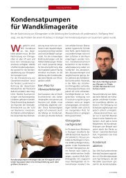
GENERAL INFORMATION<br />
WHAT IS a condensate<br />
removal pump?<br />
WHY, how?<br />
Condensates (drops of water caused by warm, humid air passing over a cold<br />
surface) are formed in air conditioning, refrigeration and condensing boiler<br />
units.<br />
There are 2 ways of removing them<br />
It is a system which consists of a pump unit and a detection unit allowing<br />
condensates to be evacuated to a water drainage outlet where there is no<br />
gravity fall.<br />
This technology has 3 advantages:<br />
❶ It protects the appearance of the customer’s installation (no<br />
unsightly pipework).<br />
Gravity evacuation<br />
Evacuate the condensates<br />
by gravity, which means<br />
dealing with technical and<br />
aesthetic problems (distant<br />
drainage outlet, not enough<br />
fall, damage to walls and<br />
unsightly pipework).<br />
The removal pump<br />
1 2<br />
Or, install a condensate<br />
removal pump (smaller<br />
dimensions, the<br />
appearance of the<br />
installation is preserved,<br />
simple and quick to<br />
install, safer as equipped<br />
with alarm and<br />
non return valve).<br />
❷ Easy, simple and safe to install.<br />
❸ Reduction of the risk of bacterial contamination by waste water<br />
(no stagnation or back-flow of water due to non return valves)<br />
There are 3 types of condensate removal <strong>pumps</strong>:<br />
PISTON<br />
IMPELLER<br />
PERISTALTIC<br />
Air<br />
conditioning<br />
Refrigeration<br />
Heating<br />
4<br />
General information<br />
5<br />
General information
WHICH operating mode?<br />
Whether monoblock or compound type, condensate removal <strong>pumps</strong><br />
operate in 3 different ways:<br />
The second<br />
is based on a float switch controlling 3 levels:<br />
❶ Reciprocating piston method<br />
These <strong>pumps</strong> are fitted with a piston which first draws in, then evacuates the<br />
condensate.<br />
❷ Centrifugal impeller method<br />
A centrifugal impeller evacuates the condensate. These <strong>pumps</strong> are intended<br />
for high flow rate requirements and are particularly suitable for contaminated<br />
condensates<br />
3<br />
1<br />
2<br />
1. On,<br />
2. Off,<br />
3. Alarm.<br />
➜ Fitted on piston <strong>pumps</strong>.<br />
❸ Peristaltic <strong>pumps</strong><br />
A roller compresses a pipe which drives out the condensates (containing<br />
contaminates or not). These <strong>pumps</strong> are self-priming and can operate dry.<br />
WHICH detection system?<br />
SAUERMANN has developed<br />
3 detection systems:<br />
The first is based on two mechanical float switches<br />
one of which controls the On/Off levels and the<br />
other the Alarm.<br />
➜ Fitted on impeller <strong>pumps</strong>.<br />
As it is largely unaffected by the nature of the condensates (oil or grease on<br />
the surface, deposits of scale, dust or algae formation) float switch detection<br />
is very reliable.<br />
The presence of an alarm level leads to increased safety.<br />
As soon as a problem is detected (abnormally high water level leading to a<br />
risk of overflow), the pump automatically cuts off the air conditioning<br />
system compressor or triggers an audible or visual alarm.<br />
Problems may be caused by different reasons:<br />
- power cut<br />
- pump stoppage<br />
- pinched pipe<br />
3<br />
The third operates by detecting a temperature difference across the cooling<br />
coil of more than 6°C between two temperature sensors.<br />
➜ Fitted on PE 5100 peristaltic <strong>pumps</strong>.<br />
On/OfF<br />
Alarm<br />
6<br />
General information<br />
7<br />
General information
HOW TO CHOOSE YOUR<br />
CONDENSATE REMOVAL PUMP<br />
<strong>SELECTING</strong> <strong>pumps</strong><br />
Piston <strong>pumps</strong> for air conditioners up to 10 kW and up to 30 kW<br />
WHICH PUMP FOR WHICH SYSTEM?<br />
Multi<br />
Cassette<br />
systems<br />
Air conditioning<br />
units<br />
Wall-mounted<br />
air conditioners<br />
Ceiling suspended<br />
DX / Chilled water<br />
fan-coil units consoles<br />
Ducted<br />
YOU NEED TO KNOW<br />
THE FOLLOWING<br />
CHARACTERISTICS:<br />
❶ The volume of condensates<br />
produced or the refrigerating<br />
capacity of your installation<br />
will give you an indication<br />
of the volume of condensates<br />
to be removed.<br />
❷ The type of appliance<br />
which you are fitting it to.<br />
Choose your pump based<br />
on these characteristics.<br />
Check that the model<br />
you choose has<br />
a sufficient flow rate /<br />
pressure ratio.<br />
APPLICATIONS<br />
AIR CONDITIONING<br />
Max cooling capacity<br />
WALL OR FLOOR<br />
MOUNTED<br />
Wall<br />
Consoles<br />
Fan-coil units<br />
Air conditioning<br />
units<br />
CEILING<br />
MOUNTED<br />
Ceiling suspended<br />
Ducted units<br />
Cassette or<br />
multi cassette systems<br />
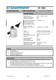
SI 1082<br />
DELTA PACK<br />
D: 8 l/h<br />
R: 6 m<br />
SI 3080<br />
D: 8 l/h<br />
A: 1 m<br />
R: 6 m<br />
SI 3100<br />
SI 2750<br />
D: 10 l/h<br />
A: 2 m<br />
R: 6 m<br />
SI 3200<br />
D: 20 l/h<br />
A: 2 m<br />
R: 6 m<br />
SI 1730<br />
D: 30 l/h<br />
A: 2,50 m<br />
R: 10 m<br />
EE 1650<br />
D: 30 l/h<br />
R: 13 m<br />
10 kW 10 kW 10 kW 20 kW 30 kW 30 kW<br />
D: Flow rate - A: Suction - R: Discharge<br />
8<br />
Selection - <strong>pumps</strong><br />
9<br />
Selection - <strong>pumps</strong>
<strong>SELECTING</strong> <strong>pumps</strong><br />
Centrifugal impeller method<br />
Multi Cassette<br />
systems<br />
Peristaltic <strong>pumps</strong><br />
Air conditioning<br />
units<br />
Wall-mounted<br />
air conditioners<br />
WHICH PUMP FOR WHICH SYSTEM?<br />
Ceiling suspended<br />
DX / Chilled water<br />
fan-coil units<br />
Ducted<br />
Refrigerated<br />
display<br />
cabinets<br />
Condensing<br />
boilers<br />
APPLICATIONS<br />
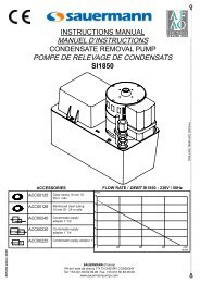
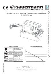
SI 1800 SI 1805 - SI 1820 SI 1822 SI 1850 PE 5000 - PE 5100 - PE 5200 PE 6250 PE 6000<br />
D: 300 l/h<br />
D: 500 l/h<br />
D: 380 l/h<br />
D: 1100 l/h<br />
R: 4,70 m<br />
R: 5,40 m<br />
R: 6,20 m<br />
R: 11 m<br />
D: 6 l/h<br />
A: 2 m<br />
R: 12 m<br />
D: 25 l/h<br />
A: 2 m<br />
R: 10 m<br />
D: 1,5 l/h<br />
A: 2 m<br />
R: 15 m<br />
AIR CONDITIONING<br />
Max cooling capacity<br />
WALL OR FLOOR<br />
MOUNTED<br />
Wall<br />
Consoles<br />
Fan-coil units<br />
Air conditioning<br />
units<br />
CEILING<br />
MOUNTED<br />
Ceiling suspended<br />
Ducted units<br />
Cassette or multi<br />
cassette systems<br />
REFRIGERATION<br />
Evaporators<br />
Display cabinets<br />
Humidifiers/<br />
dehumidifiers<br />
HEATING<br />
Gas condensing boilers<br />
AIR COOLING<br />
TOWERS<br />
D: Flow rate - A: Suction - R: Discharge<br />
8 kW<br />
10<br />
Selection - <strong>pumps</strong><br />
Please contact us should you require<br />
any assistance in selecting a pump.<br />
11<br />
Selection - <strong>pumps</strong>
Cooling capacity and<br />
examples of actual flow rates<br />
Actual flow rates for the <strong>pumps</strong><br />
SI 1082 / DELTA SI PACK 1082 -<br />
THE REFRIGERATING CAPACITY GIVES YOU<br />
THE VOLUME OF CONDENSATES TO BE REMOVED<br />
THE HEAD LOSSES DEFINED IN THIS<br />
TABLE ARE CALCULATED WITH 1/4’’<br />
FLEXIBLE PIPEWORK OF 6 MM<br />
DISCHARGE<br />
HEAD<br />
TOTAL PIPE LENGTH<br />
5 m 10 m 20 m 30 m<br />
Use the cooling capacity information supplied by the manufacturer of the air<br />
conditioner. It is generally estimated that, for normal usage conditions, the<br />
volume of condensates to be removed varies from 0.5 to 0.8 l/hr per kW of<br />
cooling capacity. This value may be doubled in very humid areas.<br />
For example: a cooling capacity of 3 kW will produce<br />
from 1.5 to 2.4 l/hr of condensates to be removed.<br />
INTERNAL DIAMETER<br />
1 m 6.8 6.3 5.3 4.3<br />
2 m 5.5 5 4.1 3.2<br />
3 m 4.2 3.8 3 2.5<br />
4 m 3 2.6 2.2 2<br />
5 m 2.2 2 1.8 1.5<br />
6 m 1.5 1.4 1.2 1<br />
Installation Overview<br />
Pour les pompes SI 1082, , SI 3080, SI 3100, SI 3200, SI 2750, SI 1730,<br />
PE 5000, PE 5100, PE 5200, PE 6250<br />
You must<br />
take into<br />
account the<br />
head loss<br />
connected<br />
with:<br />
The suction head if the pump<br />
is installed higher than the air<br />
conditioner.<br />
The discharge head<br />
The total length of the pipe<br />
Pump<br />
ACC 00205<br />
SI 1082 / DELTA PACKSI 3080<br />
THE HEAD LOSSES DEFINED IN THIS<br />
TABLE ARE CALCULATED WITH 1/4’’<br />
DISCHARGE<br />
HEAD<br />
TOTAL PIPE LENGTH<br />
FLEXIBLE PIPEWORK OF 6 MM<br />
5 m 10 m 20 m 30 m<br />
INTERNAL DIAMETER<br />
1 m 6.8 6.3 5.3 4.3<br />
SUCTION 2 m 5.5 5 4.1 3.2<br />
HEAD 3 m 4.2 3.8 3 2.5<br />
0 m 4 m 3 2.6 2.2 2<br />
5 m 2.2 2 1.8 1.5<br />
6 m 1.5 1.4 1.2<br />
Pump<br />
SI 1082<br />
ACC 00209<br />
Detection<br />
Connections are always made above the level of the pump to prevent a<br />
siphon effect in the pipes and the pump becoming unprimed (B>0).<br />
NOTE: If the discharge connection is made below the level of the pump<br />
then fit the <strong>Sauermann</strong> anti-siphon device ACC00214.<br />
1 m 5.6 5.2 4.3 3.4<br />
MAX 2 m 4.3 3.9 3.1 2.3<br />
SUCTION HEAD 3 m 3 2.7 2 1.6<br />
1 m 4 m 1.8 1.5 1.2 1.1<br />
5 m 1 0.9 0.8 0.6<br />
6 m 0.3 0.2 0.2 0.1<br />
12<br />
Selection - power<br />
13<br />
Selection - flow rates
Actual flow rates for the <strong>pumps</strong><br />
SI 1082 / DELTA SI PACK 3100 - SI 2750<br />
Actual flow rates for the <strong>pumps</strong><br />
SI 1082 / DELTA PACKSI 3200<br />
THE HEAD LOSSES DEFINED<br />
DISCHARGE<br />
THE HEAD LOSSES DEFINED<br />
DISCHARGE<br />
IN THIS TABLE ARE CALCULATED HEAD TOTAL PIPE LENGTH<br />
WITH 1/4’’ FLEXIBLE PIPEWORK 5 m 10 m 20 m 30 m<br />
OF 6 MM INTERNAL DIAMETER<br />
IN THIS TABLE ARE CALCULATED HEAD TOTAL PIPE LENGTH<br />
WITH 1/4’’ FLEXIBLE PIPEWORK OF 5 m 10 m 20 m 30 m<br />
6 MM INTERNAL DIAMETER<br />
1 m 9.5 9 8.2 7.4<br />
SUCTION 2 m 7 6.5 5.7 4.9<br />
HEAD 3 m 5 4.6 3.9 3.4<br />
0 m 4 m 4 3.6 3.1 2.8<br />
5 m 3.2 2.7 2.5 2.3<br />
6 m 2.5 2.2 2 1.8<br />
1 m 19 17.5 15.5 13.5<br />
SUCTION 2 m 17.5 16 14 12<br />
HEAD 3 m 16 14 12 10<br />
0 m 4 m 14 12 10 8.5<br />
5 m 11.5 10 8.5 7<br />
6 m 9.5 8 7 6<br />
1 m 7.5 7 6.2 5.4<br />
MAX 2 m 6 5 4.2 3.4<br />
SUCTION HEAD 3 m 4.8 3.5 2.9 2.5<br />
1 m 4 m 3.6 2.6 2.1 1.8<br />
5 m 2.2 1.7 1.5 1.3<br />
6 m 1.5 1.2 1 0.8<br />
1 m 16.5 15.5 13.5 12<br />
SUCTION 2 m 14.5 13.5 11.5 11<br />
HEAD 3 m 12.5 11.5 10.5 10<br />
1 m 4 m 10 9 8.5 8<br />
5 m 8.5 7.5 6.5 5.5<br />
6 m 7 5 4 3<br />
1 m 6.2 5.7 4.9 4.1<br />
MAX 2 m 5 4.5 3.7 2.9<br />
SUCTION HEAD 3 m 3.8 3.4 2.7 2.2<br />
2m 4 m 2.4 2 1.5 1.2<br />
5 m 1 0.5 0.3 0<br />
6 m 0.5 0 0 0<br />
1 m 13 12.5 12 11<br />
MAX 2 m 12 11.5 11 10<br />
SUCTION HEAD 3 m 11 10.5 10 9<br />
2 m 4 m 8 7.5 7 6<br />
5 m 6 5.5 5 5<br />
6 m 4 3.5 3 3<br />
14<br />
Selection - flow rates<br />
15<br />
Selection - flow rates
Actual flow rates for the <strong>pumps</strong><br />
SI 1082 / DELTA PACKSI 1730<br />
Installation overview<br />
For <strong>pumps</strong> EE1650, SI1800, SI1805, SI1820, SI1822, SI1850<br />
THE HEAD LOSSES DEFINED<br />
DISCHARGE<br />
IN THIS TABLE ARE CALCULATED HEAD TOTAL PIPE LENGTH<br />
WITH 1/4’’ FLEXIBLE PIPEWORK OF 5 m 10 m 20 m 30 m<br />
6 MM INTERNAL DIAMETER<br />
1 m 29 27 25 23<br />
SUCTION 2 m 27.5 25.5 24 22<br />
HEAD 3 m 25.5 24 22 20.5<br />
0 m 4 m 23.5 22 20 19<br />
5 m 21 19.5 18 16.5<br />
6 m 18 16.5 15 14<br />
7 m 15.5 14 12.5 11.5<br />
8 m 13 11.5 10 9<br />
9 m 10.5 9 7.5 6.5<br />
10 m 7.5 6 5 4<br />
1 m 24 22 20 20<br />
SUCTION 2 m 22 21 20 19<br />
HEAD 3 m 20 19 18 17.5<br />
1 m 4 m 17 16.5 16 15.5<br />
5 m 14.5 14 13.5 13.5<br />
6 m 12 11.5 11 11<br />
7 m 10.5 10 9.5 9<br />
8 m 8.5 8 7.5 7<br />
9 m 6.5 6 5.5 5<br />
10 m 5 4 3.5 3<br />
1 m 20 19 18 17.5<br />
MAX 2 m 17 16.5 16 15.5<br />
SUCTION HEAD 3 m 14.5 14 13.5 13.5<br />
2 m 4 m 12 11.5 11 11<br />
5 m 10.5 10 9.5 9<br />
6 m 8.5 8 7.5 7<br />
7 m 6.5 6 5.5 5<br />
8 m 5 4 3.5 3<br />
9 m 2.5 2 1.5 1<br />
PUMP<br />
PUMP<br />
or<br />
Discharge head<br />
Total pipe length<br />
Actual flow rates for the <strong>pumps</strong><br />
SI 1082 / DELTA PACKEE 1650<br />
THE HEAD LOSSES DEFINED IN THIS DISCHARGE<br />
TABLE ARE CALCULATED WITH 1/4’’<br />
HEAD<br />
TOTAL PIPE LENGTH<br />
FLEXIBLE PIPEWORK OF 6 MM INTER-<br />
5 m 10 m 20 m 30 m<br />
NAL DIAMETER<br />
1 m 29 27 25 23<br />
2 m 27.5 25.5 24 22<br />
3 m 25.5 24 22 20.5<br />
4 m 23.5 22 20 19<br />
5 m 21 19.5 18 16.5<br />
6 m 18 16.5 15 14<br />
7 m 15.5 14 12.5 11.5<br />
8 m 13 11.5 10 9<br />
9 m 10.5 9 7.5 6.5<br />
10 m 7.5 6 5 4<br />
16<br />
Selection - flow rates<br />
17<br />
Selection - flow rates
Actual flow rates for the <strong>pumps</strong><br />
SI 1082 / DELTA PACKSI 1800<br />
SI 1082 / DELTA PACKSI 1822<br />
THE HEAD LOSSES DEFINED<br />
IN THIS<br />
DISCHARGE<br />
TOTAL PIPE LENGTH<br />
THE HEAD LOSSES DEFINED<br />
IN THIS<br />
DISCHARGE<br />
TOTAL PIPE LENGTH<br />
TABLE ARE CALCULATED WITH 1/4’’<br />
HEAD 5 m 10 m 20 m 30 m<br />
TABLE ARE CALCULATED WITH 1/4’’<br />
HEAD 5 m 10 m 20 m 30 m<br />
FLEXIBLE PIPEWORK OF 10 MM<br />
(IN L/H) (IN L/H) (IN L/H) (IN L/H)<br />
FLEXIBLE PIPEWORK OF 10 MM<br />
(IN L/H) (IN L/H) (IN L/H) (IN L/H)<br />
INTERNAL DIAMETER<br />
INTERNAL DIAMETER<br />
1 m 230 180 145 120<br />
1 m 330 260 220 190<br />
2 m 165 130 100 85<br />
2 m 275 220 190 160<br />
3 m 100 80 60 50<br />
3 m 220 175 155 135<br />
4 m 40 30 20 15<br />
4 m 160 130 120 100<br />
5 m 100 80 70 60<br />
6 m 20 15 10 10<br />
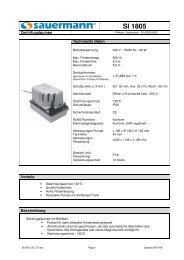
SI 1082 / DELTA PACKSI 1850<br />
SI 1082 / DELTA SI PACK 1805 - SI 1820<br />
THE HEAD LOSSES DEFINED IN THIS<br />
TABLE ARE CALCULATED WITH 1/4’’<br />
FLEXIBLE PIPEWORK OF 10 MM<br />
INTERNAL DIAMETER<br />
DISCHARGE<br />
TOTAL PIPE LENGTH<br />
HEAD 5 m 10 m 20 m 30 m<br />
(IN L/H) (IN L/H) (IN L/H) (IN L/H)<br />
1 m 460 380 280 200<br />
2 m 390 320 240 180<br />
3 m 300 250 190 150<br />
4 m 200 180 130 100<br />
5 m 90 80 60 50<br />
THE HEAD LOSSES DEFINED IN THIS<br />
TABLE ARE CALCULATED WITH 1/4’’<br />
FLEXIBLE PIPEWORK OF 10 MM<br />
INTERNAL DIAMETER<br />
DISCHARGE<br />
TOTAL PIPE LENGTH<br />
HEAD 5 m 10 m 20 m 30 m<br />
(IN L/H) (IN L/H) (IN L/H) (IN L/H)<br />
1 m 750 590 375 285<br />
2 m 675 545 345 270<br />
3 m 600 500 310 255<br />
4 m 520 460 285 235<br />
5 m 450 410 255 215<br />
6 m 355 225 190<br />
7 m 300 185 160<br />
8 m 240 145 125<br />
9 m 170 100 85<br />
10 m 85 60 45<br />
18<br />
Selection - flow rates<br />
19<br />
Selection - flow rates
Actual flow rates for the <strong>pumps</strong><br />
Technical specifications<br />
SI 1082 / PE DELTA 5000 PACK - PE 5100 - PE 5200<br />
Flow rate 6 I/h Max suction head 2 m Max vertical discharge 12 m<br />
Pumps<br />
DETECTION LEVELS<br />
+/- 2mm<br />
On Off Alarm<br />
Sound<br />
level<br />
Alarm contact at<br />
250V<br />
DIMENSIONS<br />
l x w x h in mm<br />
Pump<br />
unit<br />
Detection<br />
unit<br />
SI 1082 / DELTA PACKPE 6000<br />
Flow rate 1,5 I/h Max suction head 2 m Max vertical discharge 15 m<br />
SI 1082<br />
SI 2750<br />
SI 3080<br />
SI 3100<br />
18 12 21<br />
16 11 19<br />
21,5 dB(A)<br />
32 dB(A)<br />
20,2 dB(A)<br />
25,1 dB(A)<br />
NC<br />
NO/NC<br />
NC<br />
NC<br />
8 A resistive<br />
8 A resistive<br />
8 A resistive<br />
8 A resistive<br />
66 x 44 x 77<br />
61 x 38 x 76<br />
66 x 44 x 59<br />
66 x 44 x 59<br />
55 x 38 x 36<br />
55 x 38 x 36<br />
55 x 38 x 36<br />
SI 1082 / DELTA PACKPE 6250<br />
Flow rate 25 I/h Max suction head 2 m Max vertical discharge 10 m<br />
SI 3200<br />
SI 1730<br />
17 11 21<br />
32,4 dB(A)<br />
42 dB(A)<br />
NC<br />
NO/NC<br />
8 A resistive<br />
8 A resistive<br />
66 x 44 x 59<br />
74 x 52 x 95<br />
55 x 38 x 36<br />
55 x 38 x 36<br />
PE 5000<br />
30 dB(A)<br />
109 x 110 x 91<br />
PE 5100<br />
30 dB(A)<br />
NC<br />
8 A resistive<br />
109 x 110 x 91<br />
PE 5200<br />
16 11 19<br />
30 dB(A)<br />
109 x 110 x 91<br />
55 x 38 x 36<br />
MONOBLOCK PUMPS WITH TANK<br />
Pumps<br />
On Off Alarm<br />
Sound<br />
level<br />
Alarm contact at<br />
250V<br />
Pump<br />
unit<br />
Detection<br />
unit<br />
EE 1650<br />
Under the tank 16 10 21 52 dB(A) NC 8 A resistive 160 x 85 x 88<br />
0,5 l<br />
In the tank 21 15 26 52 dB(A) NC 8 A resistive 160 x 85 x 88<br />
0,5 l<br />
SI 1800<br />
40<br />
28<br />
66<br />
54 dB(A)<br />
NC<br />
4 A resistive<br />
283 x 127 x 161<br />
2 l<br />
SI 1805<br />
24<br />
13<br />
30<br />
47 dB(A)<br />
NC<br />
4 A resistive<br />
195 x 130 x 122<br />
0,5 l<br />
SI 1820<br />
43<br />
27<br />
67<br />
47 dB(A)<br />
NC<br />
4 A resistive<br />
195 x 130 x 170<br />
2 l<br />
SI 1822<br />
75<br />
20<br />
90<br />
47 dB(A)<br />
NC<br />
4 A resistive<br />
305 x 152 x 235<br />
3,8 l<br />
SI 1850<br />
70<br />
20<br />
95<br />
66 dB(A)<br />
NC<br />
4 A resistive<br />
305 x 152 x 257<br />
3,8 l<br />
20<br />
Selection - flow rates<br />
21<br />
Selection – detection levels
HOW TO INSTALL YOUR<br />
CONDENSATE REMOVAL PUMP<br />
A few Basic Rules<br />
IMPORTANT NOTE ON<br />
COMMISSIONING PUMPS<br />
WITH REMOTE DETECTION<br />
Before installation, thoroughly rinse the coil<br />
and the condensates collection tank to<br />
remove any foreign bodies and metal<br />
particles.<br />
When the pump has a separate detection<br />
unit, it must be fixed horizontally on a<br />
support.<br />
Monoblock tank <strong>pumps</strong> must always be fitted<br />
horizontally on a support.<br />
Before carrying out<br />
any operation on<br />
the pump, make<br />
sure the installation<br />
is disconnected from<br />
the power supply.<br />
To ensure that the <strong>pumps</strong> function correctly in<br />
the future, ensure that when you first commission<br />
them (and after each maintenance operation)<br />
the <strong>pumps</strong> are properly primed.<br />
Check that the suction pipe (between the<br />
detection unit and the pump) and part of the<br />
discharge pipe are filled with water.<br />
Failure to observe these rules can lead to poor results (tank overflow, high<br />
noise level, abnormal overheating etc.) which are both inconvenient for the<br />
end user and costly for the installer.<br />
You can use the priming squeezie<br />
bottle ACC 00401.<br />
YOU ARE STRONGLY ADVISED TO AVOID THE USE OF DETERGENT OR AGGRES-<br />
SIVE PRODUCTS WHEN CLEANING THE TANK OF MONOBLOCK PUMPS<br />
22<br />
Installation - rules<br />
23<br />
Installation - rules
Piston pump with integral detection<br />
Piston pump with integral detection<br />
Ready to fit assembly for wall-mounted air<br />
conditioners up to 10 kW<br />
READY TO FIT<br />
Delta Pack comprises:<br />
- a mini pump with integral detection SI 1082<br />
- a complete assembly kit containing:<br />
• a clip-on cover,<br />
• 75 cm of 80 x 60 mm duct,<br />
• all assembly accessories.<br />
AIR<br />
CONDITIONING<br />
REVERSIBLE LEFT OR<br />
RIGHT ASSEMBLY<br />
Installation template<br />
supplied<br />
INSTRUCTIONS INSTALLATION SI 1082<br />
Allows the pump to be assembled on the left or right of the air conditioner.<br />
Reversible anti-vibration<br />
PRACTICAL CLIP-ON<br />
COMPONENTS<br />
Support antivibratoir<br />
réversible<br />
Simple electrical connection<br />
Raccordement électronique<br />
simplifié<br />
LARGE AREA<br />
FOR<br />
COOLING PIPES<br />
support<br />
Clip-on pipe, elbow and ceiling duct<br />
ACC 00105 / ACC 00150 / ACC 00151<br />
Clear tubing 6 mm<br />
ACC 00105: 5m in blister pack<br />
ACC 00150: in 50m roll<br />
ACC 00151: reinforced, 50m roll<br />
Can be used for routing cooling pipes<br />
up to diameter 5/8" - 3/8"<br />
RECOMMENDED ACCESSORIES<br />
ACC 00205<br />
6 self-sealing fitting for<br />
condensate removal.<br />
For an SI 1082 pump sold individually,<br />
the connection should be made directly<br />
at the tank outlet.<br />
You can use connector ACC 00209<br />
Carry out an in situ test and prime the pump.<br />
To do this, gently fill with water using the priming squeezie bottle (ACC 00401).<br />
24 Installation - <strong>pumps</strong> with integrated detection<br />
25<br />
Installation - <strong>pumps</strong> with integrated detection
Piston <strong>pumps</strong> with remote detection<br />
SI 3080 /SI 3100 / SI 3200 / SI 2750 / SI 1730<br />
Piston <strong>pumps</strong> with remote detection<br />
SI 3080 / SI 3100 / SI 3200 / SI 2750 / SI 1730<br />
AIR<br />
CONDITIONING<br />
SILENT<br />
SI 3080, SI 3100 up to 10 kW /<br />
SI 3200 up to 20 kW<br />
DETECTION UNIT INSTALLATION<br />
The vent pipe allows the air to be bled from the detection unit. You are advised<br />
to use the 4 mm clear tube supplied. Its length allows the upper level of the<br />
tube to be slightly above the maximum level of the condensates drain tank. In<br />
the event of a fault, this avoids overspill (principle of communicating vessels).<br />
When commissioning, ensure that this breather tube does not contain any<br />
water.<br />
Do not use a longer tube than the one supplied.<br />
SI 2750<br />
up to 10 kW<br />
FRONT<br />
SI 1730<br />
up to 30 kW<br />
The detection unit can be connected either<br />
at the front or the rear.<br />
REAR*<br />
*Supplied as standard: outlet at back.<br />
Blank the unused outlet with the plug<br />
supplied.<br />
The detection unit can be connected in 3 ways:<br />
Assembly position of the detection unit<br />
0/+ 15° +/- 15°<br />
At the outlet of the<br />
condensate evacuation tube<br />
At the tank outlet<br />
Directly inside the tank<br />
Front outlet<br />
Position to<br />
be avoided<br />
Acceptable<br />
position<br />
Rear outlet<br />
Position to<br />
be avoided<br />
Acceptable<br />
position<br />
26<br />
Installation - <strong>pumps</strong> with remote detection<br />
27<br />
Installation - <strong>pumps</strong> with remote detection
Piston <strong>pumps</strong> with remote detection<br />
SI 3080 / SI 3100 / SI 3200 / SI 2750/ SI 1730<br />
Monoblock pump with tank<br />
EE 1650 Monoblock pump with integrated tank for air conditioners up to 30 kW<br />
AIR<br />
CONDITIONING<br />
AIR<br />
CONDITIONING<br />
Silent<br />
Powerful<br />
Carry out an in situ test and<br />
prime the pump. To do this,<br />
gently fill with water using the<br />
priming squeezie bottle<br />
(ACC 00401).<br />
EE 1650<br />
up to 30 kW<br />
tank: 0.5 l<br />
PUMP UNIT INSTALLATION<br />
INSTALLATION<br />
The recommended fitting positions for the<br />
pump are: (avoid all other positions)<br />
Acceptable<br />
position<br />
Recommended<br />
position<br />
The pump must not be<br />
splashed nor located in a<br />
damp environment.<br />
the pump collects<br />
the condensates via<br />
the gravity inlet<br />
(in the top)<br />
The pump can be connected in 2 ways:<br />
The pump is<br />
placed directly in<br />
the condensate<br />
collecting tank<br />
Vertical discharge guarantees that the non<br />
return valve is watertight.<br />
The electrical connection must always be<br />
above the water inlet/outlet.<br />
Ensure that the condensates<br />
pass<br />
through the pump in<br />
the correct direction<br />
(see arrow on unit)<br />
RECOMMENDED ACCESSORIES<br />
Water may accumulate from<br />
condensation in the tube or<br />
due to a leak from the clear<br />
tube/pump end piece<br />
connection.<br />
ACC 00205<br />
6 self-sealing fittings for<br />
condensate removal.<br />
To use an EE 1650 in a condensate collecting<br />
tank, where the condensates are fed from<br />
below, follow the procedure outlined below.<br />
CAUTION<br />
irreversible<br />
procedure<br />
RECOMMENDED ACCESSORIES<br />
Clean the filter<br />
every time the air<br />
conditioner is<br />
inspected<br />
ACC 00105 / ACC 00150 / ACC 00151<br />
ACC 17010<br />
ACC 00205<br />
ACC 00105/ACC 00150/ACC 00151<br />
Clear tubing 6 mm<br />
ACC 00105: 5m in blister pack<br />
ACC 00150: in 50m roll<br />
ACC 00151: reinforced, 50m roll<br />
In-line filter for SI 1730.<br />
6 self-sealing fittings for<br />
condensate removal.<br />
ACC 00105: 5 m in blister pack<br />
ACC 00150: in 50 m roll<br />
ACC 00151: reinforced, 50m roll<br />
28<br />
Installation - <strong>pumps</strong> with remote detection<br />
29<br />
Installation - monoblock <strong>pumps</strong> with tank
Monoblock impeller <strong>pumps</strong> with tank<br />
SI 1800 / SI 1805 / SI 1820 / SI 1822 / SI 1850<br />
Monoblock impeller <strong>pumps</strong> with tank<br />
SI 1800 / SI 1805 / SI 1820 / SI 1822 / SI 1850<br />
AIR<br />
CONDITIONING<br />
HEATING<br />
REFRIGERATION<br />
Dynamic<br />
SI 1800<br />
tank: 2 l<br />
SI 1820<br />
tank: 2 l<br />
SI 1805<br />
tank: 0.5 l<br />
SI 1822<br />
tank: 3.8 l<br />
SI 1850<br />
tank: 3.8 l<br />
INSTALLATION<br />
MAINTENANCE<br />
REMOVING THE VALVE<br />
The transport<br />
tear-off strip<br />
must be removed<br />
before starting.<br />
Inlet<br />
adaptor<br />
ACC 00225<br />
ACC 00230<br />
ACC 00240<br />
The pump<br />
collects the<br />
condensates<br />
via the inlet<br />
in the top.<br />
The inside of the pump<br />
must be regularly<br />
cleaned. For this we<br />
recommend that you<br />
use a solution containing<br />
5% bleach. Ensure that<br />
the float switches remain<br />
clean.<br />
MECHANICAL ASSEMBLY<br />
All monoblock impeller <strong>pumps</strong> have a reversible tank.<br />
Condensate inlet<br />
Condensate inlet<br />
on left<br />
on right<br />
ACC 00110<br />
Installation kit::<br />
1 x ACC 00225,<br />
1 X ACC 00230,<br />
1 X ACC 00240.<br />
RECOMMENDED ACCESSORIES<br />
ACC 00810<br />
for SI 1805, SI 1820<br />
Non return valve<br />
Ø 10 mm<br />
ACC 00601<br />
Control switch.<br />
Used to control an<br />
additional alarm.<br />
ACC 00125 / ACC 00126<br />
Clear tubing<br />
Ø10 mm, length 25 m<br />
ACC 00125: non-reinforced tube<br />
ACC 00126: reinforced tube<br />
ACC 00225/ACC 00230/ACC 00240<br />
Condensate inlet adapters<br />
ACC 00225: 1”, Ø 32 mm<br />
ACC 00230: 1” 1/4, Ø 32 mm<br />
ACC 00240: 1” 1/2, Ø 40 mm<br />
30<br />
Installation -<br />
monoblock impeller<br />
<strong>pumps</strong> with tank<br />
31<br />
Installation -<br />
monoblock impeller<br />
<strong>pumps</strong> with tank
Peristaltic <strong>pumps</strong><br />
PE 5000 / PE 5100 / PE 5200 / PE 6250<br />
Peristaltic <strong>pumps</strong><br />
PE 5000 / PE 5100 / PE 5200 / PE 6250<br />
PRACTICAL<br />
AIR<br />
CONDITIONING<br />
REFRIGERATION<br />
PE 5100<br />
Temperature<br />
sensor for the<br />
evaporator<br />
AIR<br />
CONDITIONING<br />
REFRIGERATION<br />
PE 5000<br />
PE 5003<br />
PE 5100<br />
There are 3 different models and therefore 3 possible installations:<br />
PE 5000<br />
OPERATION<br />
INSTALLATION PE 5000<br />
Condensates are removed from the air<br />
conditioning unit at the tank outlet via a<br />
6 x 9 mm tube and the PE 5003 connector<br />
supplied with the pump.<br />
Pump operation is dependent on the operation of the air conditioning compressor<br />
or whenever the system provides cooling. The pump will continue to<br />
run for three minutes after the compressor has stopped.<br />
Installation example for<br />
PE 5000 and PE 5100 <strong>pumps</strong><br />
Rubber Outlet<br />
Connector (supplied)<br />
PE 5003<br />
Ø6 mm<br />
connector<br />
(supplied)<br />
Replacement head<br />
PE 5001<br />
INSTALLATION PE 5100<br />
Condensates are removed from the air<br />
conditioning unit at the tank outlet via a 6<br />
x 9 mm tube and the PE 5003 connector<br />
supplied with the pump.<br />
OPERATION<br />
The pump switches on when the temperature<br />
difference across the coil as measured<br />
by the two sensors is more than 6°C.<br />
The pump stops 3 minutes after the temperature<br />
difference falls below 6° C.<br />
Replacement head available<br />
for peristaltic <strong>pumps</strong><br />
PE 5000 / PE 5100 / PE 5200<br />
32<br />
Installation - Peristaltic <strong>pumps</strong><br />
33<br />
Installation - Peristaltic <strong>pumps</strong>
Peristaltic <strong>pumps</strong><br />
PE 5000 / PE 5100 / PE 5200 / PE 6250<br />
Peristaltic <strong>pumps</strong><br />
PE 5000 / PE 5100 / PE 5200 / PE 6250<br />
AIR<br />
CONDITIONING<br />
REFRIGERATION<br />
AIR<br />
CONDITIONING<br />
REFRIGERATION<br />
PRACTICAL<br />
PE 5200 PE 6250<br />
Ø 10 mm tube<br />
PE 5200<br />
Carry out an in situ test<br />
and prime the pump. To<br />
do this, gently fill with<br />
water using the priming<br />
squeezie bottle (ACC00401).<br />
Press the test button on the PE<br />
5000 & PE 5100 to operate the<br />
pump for three minutes.<br />
INSTALLATION PE 5200<br />
The detection unit is connected to the<br />
condensate evacuation tube outlet or<br />
directly to the tank outlet. The pump is<br />
connected to the detection unit by a 6 x<br />
9 mm tube.<br />
OPERATION<br />
The pump operates when condensates<br />
enter the detection unit. In this configuration,<br />
a 230 V / 8 A NC alarm contact is<br />
available.<br />
MAINTENANCE PE 5000/ PE 5100<br />
PE 5200<br />
Replace the tube (PE 5002) at least every<br />
year and the pump head (PE 5001) every<br />
two years or as required. (Remove the<br />
4 screws, disconnect the connector and fit<br />
the new head).<br />
Very heavily contaminated condensates can be evacuated with this high<br />
flow rate pump and its 10 mm evacuation pipe.<br />
The accessory supplied (ACC 00601), to be secured in the condensate<br />
tank, switches the pump on and off. It can also be used as an alarm contact<br />
in the event of a tank overflow.<br />
RECOMMENDED<br />
ACCESSORIES for PE 6250<br />
ACC 00125 / ACC 00126<br />
Clear tubing<br />
Ø 10 mm, length 25 m<br />
ACC 00125: non-reinforced tube<br />
ACC 00126: reinforced tube<br />
RECOMMENDED<br />
ACCESSORIES<br />
for all peristaltic<br />
<strong>pumps</strong><br />
PE 5002<br />
Replacement tube<br />
for <strong>pumps</strong><br />
PE 5000, PE 5100<br />
and PE 5200<br />
ACC 00205<br />
6 self-sealing<br />
fittings<br />
condensate<br />
removal<br />
PE 5001<br />
Replacement head<br />
for <strong>pumps</strong><br />
PE 5000, PE 5100<br />
and PE 5200<br />
ACCESSORY<br />
SUPPLIED for PE 6250<br />
ACC 00601<br />
Float control switch. Used<br />
to control the pump or an<br />
alarm.<br />
ACC 00601<br />
Control switch.<br />
Used to control an additional<br />
alarm<br />
PE 5003<br />
Ø 6 mm / Ø 17 mm<br />
adaptor with rubber<br />
tube<br />
34<br />
Installation - Peristaltic <strong>pumps</strong><br />
35<br />
Installation - Peristaltic <strong>pumps</strong>
DOSING peristaltic pump<br />
PE 6000<br />
AIR<br />
CONDITIONING<br />
Wiring DIAGRAM for <strong>pumps</strong> SI 1082, DELTA PACK, SI 3080,<br />
SI 3100, SI 3200, EE 1650, SI 1730<br />
PREVENTATIVE<br />
Mains supply 230 V ~ 50/60 Hz<br />
P<br />
N<br />
EFFECTIVE AND PREVENTATIVE<br />
PE 6000<br />
Injecting disinfectant and anti-bacterial products* can sanitise air cooling towers<br />
and prevent the transmission of bacteria (Legionnaire's disease) and the<br />
formation of algae.<br />
(*products not supplied, usage frequency, concentration and dosage in accordance with<br />
product manufacturers' recommendations).<br />
Connector<br />
Pump<br />
P N C NC<br />
Lead<br />
Connection unit<br />
630 mA fuse<br />
Solenoid valve<br />
Compressor<br />
NC/NO alarm contact,<br />
only on SI 1730<br />
PROGRAMMABLE<br />
or<br />
• In 15 minute intervals on a front-mounted time clock.<br />
• Timer-controlled programmable injection duration of 2 - 18 minutes.<br />
ACCESSORIES SUPPLIED<br />
Accessory supplied<br />
Accessory supplied<br />
Accessory supplied<br />
Accessory supplied<br />
Ø 4 mm suction<br />
Ø 4 mm discharge<br />
Suction strainer<br />
Injection connec-<br />
tube (length 3m)<br />
tube (length 3m)<br />
tor with valve<br />
36<br />
37<br />
Installation - Connection
Wiring DIAGRAM for <strong>pumps</strong> SI 2750<br />
Wiring DIAGRAM for <strong>pumps</strong> PE 5000, PE 5100 AND PE 5200<br />
Mains supply 230 V ~ 50/60 Hz<br />
P N<br />
Detection connector<br />
630 mA fuse<br />
Solenoid valve<br />
Phase<br />
Neutral<br />
Compressor<br />
PE 5000<br />
Compressor<br />
P N<br />
C NCNO<br />
Audible signal<br />
Visual signal<br />
Phase<br />
Neutral<br />
PE 5100<br />
or<br />
and/or<br />
or<br />
The 8 A 250 V alarm contact<br />
(resistive) must be<br />
connected (PE 5200).<br />
Alarm<br />
C<br />
N.C.<br />
PE 5200<br />
Phase<br />
Neutral<br />
Wiring DIAGRAM for <strong>pumps</strong> SI 1800, SI 1805, SI 1820,<br />
SI 1822, SI 1850<br />
Mains supply<br />
230 V ~ 50/60 Hz<br />
P<br />
N<br />
*<br />
Pump<br />
NC/C<br />
alarm<br />
lead<br />
630 mA fuse<br />
Solenoid valve<br />
Compressor<br />
IMPORTANT<br />
The <strong>pumps</strong> must have<br />
a power supply that is<br />
independent to that of the air<br />
conditioner to ensure that<br />
they continue to operate<br />
if the refrigerating appliance<br />
breaks down.<br />
Adaptor unit<br />
or<br />
230 V<br />
48 V max<br />
* plug not supplied on SI 1800, SI 1822 and SI 1850<br />
38<br />
Installation - Connection<br />
39<br />
Installation - Connection
Alarm operating<br />
EXAMPLES<br />
Chilled water Monosplit and Multisplit<br />
Direct expansion Multisplit<br />
Production of<br />
chilled water<br />
Air conditioners<br />
Pumps<br />
External unit Air conditioners Pumps<br />
When the alarm is triggered, the pump solenoid valve is cut off<br />
and/or an audible or visual alarm is operated<br />
When the alarm is triggered, the pump solenoid valve is cut off<br />
and/or an audible or visual alarm is operated<br />
Direct expansion Monosplit<br />
External unit Air conditioners Pumps<br />
When the alarm is triggered, the pump compressor is cut off<br />
and/or an audible or visual alarm is operated.<br />
40<br />
Installation - alarm<br />
41<br />
Installation - alarm
ACCESSORIES*:<br />
LES ACCESSOIRES:<br />
ESSENTIALS LES INDISPENSABLES<br />
* Accessories are only guaranteed for the applications for which they are recommended.<br />
ACC 00209<br />
ACC 00210<br />
ACC 00211<br />
15 x 15 mm flexible connector used<br />
to drain the tank completely.<br />
90° elbow, 17 x 15 mm<br />
Ø 6 mm Tee connector<br />
Piston <strong>pumps</strong> for air conditioners up to 10 kW<br />
and up to 30 kW<br />
Centrifugal impeller method<br />
Peristaltic <strong>pumps</strong><br />
ACC 00100<br />
ACC 00105<br />
ACC 00150<br />
ACC 00151<br />
Installation kit SI 2750<br />
ACC 00105: 5m in blister pack<br />
ACC 00150: in 50m roll<br />
ACC 00151: reinforced, 50m roll<br />
ACC 00214<br />
ACC 00225<br />
ACC 00230<br />
ACC 00240<br />
ACC 00401<br />
ACC 00501<br />
To prevent siphoning when<br />
the discharge point is lower than the detector level<br />
Condensate inlet adaptors.<br />
Squeezie bottle: used to test the pump<br />
without removing the unit.<br />
10 double-sided stickers.<br />
ACC 00106<br />
Blond rubber 50 cm for SI 1082 / SI 2750 /<br />
SI 3080 / SI 3100 / SI 3200 / SI 1730<br />
ACC 00601<br />
Float control switch. Used to control the pump<br />
or an alarm SI 1800 / SI 1805 / SI 1820 /<br />
SI 1822 / SI 1850 / PE 5000 / PE 5100 / PE 6250.<br />
ACC 00110<br />
Installation kit comprising the following<br />
components: 1 X ACC 00225,<br />
1 X ACC 00230, 1 X ACC 00240.<br />
ACC 00703<br />
3 m extension for SI 2750 / SI 3080<br />
SI 3100 / SI 3200 / SI 1730 / PE 5200.<br />
ACC 00125<br />
ACC 00126<br />
Clear tube, 10 mm int. On 25 m coil<br />
ACC 00125: non-reinforced tube<br />
ACC 00126: reinforced tube<br />
ACC 00705<br />
5 m extension for SI 2750 / SI 3080<br />
SI 3100 / SI 3100 / SI 3200 / SI 1730 / PE 5200.<br />
ACC 00201<br />
Ø 17 / Ø 22 mm adaptor kit<br />
ACC 00801<br />
10 mm non return valves<br />
for SI 1805 / SI 1820.<br />
ACC 00202<br />
Ø 17 / Ø 32 mm adaptor kit<br />
ACC 00805<br />
5 non return valves for Ø 6 mm tube.<br />
ACC 00203<br />
Ø 17 / Ø 32 mm reduction for reducing flow<br />
ACC 17010<br />
In-line filter for SI 1730.<br />
ACC 00204<br />
5 Ø 6 mm straight connectors<br />
+ 5 Ø 6 mm elbow connectors.<br />
PE 5001<br />
Replacement head<br />
For <strong>pumps</strong> PE 5000 / PE 5100 / PE 5200<br />
ACC 00205<br />
6 condensate self-sealing evacuation connectors.<br />
PE 5002<br />
Replacement tube<br />
For <strong>pumps</strong> PE 5000 / PE 5100 / PE 5200<br />
ACC 00208<br />
90° elbow, 15 x 15 mm<br />
PE 5003<br />
Ø 17 mm - Ø 6 mm reduction<br />
for <strong>pumps</strong> PE 5000 / PE 5100 / PE 5200<br />
42<br />
Accessories<br />
43<br />
Accessories
QUALITY, GUARANTEE,<br />
SERVICE<br />
Our priorities<br />
At your service<br />
To anticipate your requirements, meet your expectations in full and provide<br />
total satisfaction:<br />
In practice, our quality policy continues in day to day life through the implementation<br />
of customer services:<br />
In 1997, <strong>Sauermann</strong> committed itself to implementing a quality policy in accordance<br />
with standard ISO 9002.<br />
In 2003, <strong>Sauermann</strong> applied to obtain standard ISO 9001 version 2000 and was<br />
successful in obtaining it.<br />
➜ Technical assistance which, with just one phone call, can provide you<br />
with advice and offer the best tips and information.<br />
➜ Products guaranteed for 24 months.<br />
Through regular internal audits, standard ISO 9001 version 2000 shows the<br />
total involvement at all levels of the company to ensure we constantly work<br />
towards:<br />
➜ An effective after sales department.<br />
(Products returned to the after sales department are analysed, thus<br />
helping to improve our products on a permanent basis).<br />
➜ Complying with our lead-times<br />
➜ Controlling our products<br />
➜ And improving our services.<br />
Our quality requirement continues through developing our products which<br />
are subject to certification with the main independent laboratories, in order<br />
to obtain the CE, VDE and ETL labels.<br />
44<br />
45
NOTES<br />
THE BENCHMARK RANGE OF CONDENSATE REMOVAL PUMPS<br />
46<br />
47
®<br />
SAUERMANN FRANCE<br />
Parc d’activités de l’Orée de Chevry<br />
Route de Férolles<br />
77173 CHEVRY-COSSIGNY / France<br />
Tél. : (+33) 01 60 62 06 06<br />
Fax : (+33) 01 60 62 09 09<br />
E-mail : info@sauermann.fr<br />
SAUERMANN N.A. Corp<br />
<strong>Sauermann</strong> NA Corp<br />
85 Nicon Court, Suite 1,<br />
Hauppauge, NY 11788 - USA<br />
Tél. : (+1) 631-234-7600<br />
Fax : (+1) 631-234-7605<br />
E-mail : sales@sauermann.us<br />
SAUERMANN ITALIA S.R.L.<br />
Via G. Golini 61/11<br />
40024 Castel S.Pietro Terme (BO) / Italy<br />
Tél. : (+39)-051-6951033<br />
Fax : (+39)-051-942254<br />
E-mail : info@sauermann.it<br />
SAUERMANN GmbH<br />
Kernerstrasse 18<br />
D-74223 FLEIN / Germany<br />
Tél. : (+49) 07131/399990<br />
Fax : (+49) 07131/399992<br />
E-mail : <strong>Sauermann</strong>-Flein@t-online.de<br />
SAUERMANN UK Ltd<br />
Units 7 - 9, Trident Business Park<br />
Amy Johnson Way<br />
Blackpool - Lancashire FY4 2RP<br />
United Kingdom<br />
Tél. : + 44 (0) 870 950 6378<br />
Fax : + 44 (0) 870 950 6379<br />
E-mail : sales@sauermann-uk.com<br />
www.sauermann<strong>pumps</strong>.com<br />
®<br />
is a registered trademark of <strong>Sauermann</strong> Industrie<br />
SAUERMANN SHANGHAI Co. Ltd.<br />
155 ZhangPu Road<br />
JuYuan Development Park<br />
JiaDing District<br />
Shanghai 201821 / P.R. China<br />
Tél. : (+ 86) 21 691 689 61<br />
Fax : (+ 86) 21 691 689 62<br />
E-mail : sales@sauermann.com.cn<br />
SAUERMANN Hong Kong Ltd<br />
Room 1106, Tower 1 , Lippo centre<br />
89, Queensway / Hong Kong SAR<br />
SCANDINAVIA, BALTICS, RUSSIA<br />
Parkgade 8<br />
6440 AUGUSTENBORG / Denmark<br />
Tél. : (+45) 74 47 10 78<br />
Mobil : (+45) 40 59 10 78<br />
E-mail : peter.remontius@get2net.dk<br />
PENíNSULA IBÉRICA<br />
C/Ribera del Sena, s/n-Edificio APOT-3°<br />
28042 MADRID / Spain<br />
Tél. : (+34) 637 74 74 59<br />
Fax : (+34) 91 532 87 37<br />
E-mail : castelaosauermann@lycos.es<br />
Doc UK LIV/7 - 11/07 - 5 000 ex GASOLINE