English User's Manual - Extech Instruments
English User's Manual - Extech Instruments
English User's Manual - Extech Instruments

You also want an ePaper? Increase the reach of your titles
YUMPU automatically turns print PDFs into web optimized ePapers that Google loves.
USER GUIDE<br />
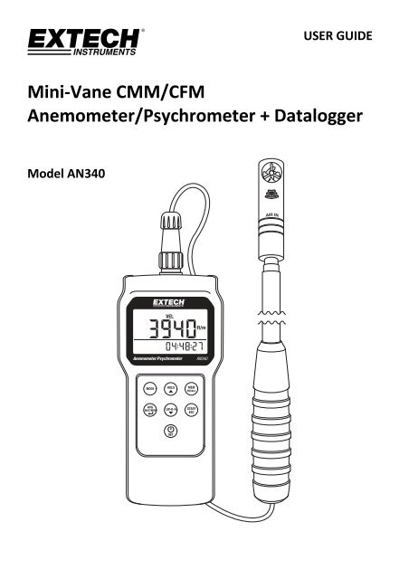
Mini‐Vane CMM/CFM<br />
Anemometer/Psychrometer + Datalogger<br />
Model AN340
Introduction<br />
Thank you for selecting the <strong>Extech</strong> AN340 CMM/CFM Anemometer Psychrometer Datalogger. This<br />
instrument measures Air Velocity, Air Flow (volume), Air Temperature, Relative Humidity, Wet Bulb<br />
Temperature, and Dew Point Temperature.<br />
The meter’s compact mini impeller is perfect for duct airflow measurements. The sensor probe has<br />
an 18mm (0.7”) diameter and a 1M (39”) telescoping probe wand with a marked scale. Duct<br />
temperature does not affect the airflow measurement results. Temperature and humidity sensors<br />
are built into the vane sensor.<br />
The user can manually store and recall 99 readings directly on the meter’s LCD. The user can also<br />
automatically log up to 12,000 readings with date and time stamp and selectable sampling rate.<br />
Readings are transferred to a PC using the supplied PC software and USB connector cable.<br />
This meter is shipped fully tested and calibrated and, with proper use, will provide years of reliable<br />
service. Please visit our website (www.extech.com) to check for the latest version of this User<br />
Guide, Product Updates, and Customer Support.<br />
CAUTIONS<br />
Improper use of this meter can cause damage to the meter and personal injury. Read and<br />
understand this user manual before operating the meter.<br />
Inspect the condition of the probe and the meter for any damage before operating the<br />
meter. Repair or replace damage before use.<br />
If the equipment is used in a manner not specified by the manufacturer, the protection<br />
provided by the equipment may be impaired.<br />
This device should not be made available to children. It contains hazardous objects as well<br />
as small parts that can be accidentally swallowed. The meter’s batteries and packing<br />
materials can also be dangerous to children.<br />
In the event that the meter is to be unused for an extended period of time, remove the<br />
batteries to protect against battery leakage.<br />
Expired or damaged batteries can be hazardous if allowed to come in contact with skin. Use<br />
suitable hand protection in such cases.<br />
Do not short circuit batteries or put batteries in fire.<br />
2<br />
AN340-EU-EN V1.3 4/13
Description<br />
Meter and Sensor Description<br />
1. Sensor connection to the meter<br />
2. Main LCD display digits<br />
3. Lower line LCD display digits<br />
4. MODE button<br />
5. AVG‐MAX‐MIN and ENTER button<br />
6. POWER ON‐OFF and SET button<br />
7. HOLD and up arrow button<br />
8. MEM and RECALL button<br />
9. START and ESC button<br />
10. LW‐D‐A and down arrow button<br />
11. Mini‐Vane impeller<br />
12. Temperature and humidity sensors<br />
13. Telescoping sensor arm<br />
Note: Battery compartment (not shown) is located on rear of instrument<br />
Meter Top Description<br />
1. Sensor connection jack<br />
2. AC power adaptor jack<br />
3. USB PC interface jack<br />
Keypad Description<br />
POWER ON‐OFF and SET button<br />
Press momentarily to power meter ON or OFF. Press and hold for two (2) seconds to enter the SETUP mode.<br />
3<br />
AN340-EU-EN V1.3 4/13
MODE button<br />
Momentary press to step through the available modes: air velocity, air volume, air temperature, relative<br />
humidity, wet bulb temperature, dew point temperature.<br />
AVERAGE, MAXIMUM, MINIMUM, and ENTER button<br />
Press to view average/minimum/maximum readings. Also used to confirm (enter) a selection while<br />
programming.<br />
START, ESC button<br />
In the normal operating mode, press and hold for two (2) seconds to start or stop the automatic datalogger.<br />
Also, press to exit (escape) AVG/MIN/MAX, RECALL, and SETUP modes.<br />
HOLD, UP ARROW button<br />
In the normal mode, press to freeze/un‐freeze the displayed reading. It is also used to move UP in a menu list.<br />
LW‐D‐A (LENGTH/WIDTH‐DIAMETER‐AREA) button<br />
In the Air Volume mode, press this button to begin programming the AREA value for the duct under test. This<br />
button is also used to move DOWN a menu list.<br />
MEM‐RECALL button<br />
In the normal mode of operation, press this button to manually record a reading into the meter’s 99 location<br />
memory. Press and hold for two (2) seconds to recall and review the manually recorded data one reading at a<br />
time.<br />
and<br />
With the meter OFF, press and hold these two buttons to disable the sleep mode. Sleep mode switches the<br />
meter off automatically after a twenty (20) minute period of inactivity.<br />
and<br />
With the meter OFF, press and hold these two buttons until PC appears on the LCD. The meter is now ready to<br />
communicate with a PC. For instructions on the use of the PC interface please refer to the HELP utility provided<br />
on the supplied CD‐ROM.<br />
4<br />
AN340-EU-EN V1.3 4/13
Display Icon Description<br />
MAX‐MIN‐AVG Maximum, Minimum, and Average readings<br />
LW Length and Width (for rectangular duct area measurements)<br />
D Diameter (for circular duct area measurements)<br />
A Area for duct measurements<br />
Cm 2 and inch 2<br />
o C/F Temperature units<br />
TA Air Temperature<br />
RH Relative Humidity<br />
DP Dew point<br />
WBT Wet bulb<br />
VEL Velocity<br />
VOL Volume<br />
HOLD Display HOLD feature<br />
Square centimeters and square inches for area measurements<br />
%rh Relative Humidity unit of measure<br />
m/s Meters per second<br />
ft/m Feet per minute<br />
CFM Cubic feet per minute<br />
CMM Cubic meters per minute<br />
REC Record<br />
RECALL Recall<br />
AM/PM Morning/Evening time<br />
B Low Battery<br />
8888.8 Main (larger and upper) display digits<br />
88‐88‐88 Timer (lower) display digits<br />
5<br />
AN340-EU-EN V1.3 4/13
Operation<br />
Power ON‐OFF<br />
1. Switch the meter ON by pressing the power button momentarily.<br />
2. Press again to switch the meter OFF.<br />
3. If the meter does not switch ON, check that the meter has six (6) fresh AAA batteries<br />
installed in the rear battery compartment. Refer to the battery installation section for<br />
details.<br />
4. The meter can also be powered using the 9V AC power adaptor. The power adaptor connects<br />
to the top of the meter using the jack as shown in the Description section of this guide.<br />
Sleep mode<br />
The meter will automatically enter the sleep mode (switch off) after twenty (20) minutes of<br />
inactivity. To disable this feature: with the meter OFF, press and hold the SET and HOLD buttons<br />
for two (2) seconds. The LCD will display 'n' as it switches ON. Now the sleep mode is disabled<br />
and the user must press the power button momentarily to switch the meter OFF.<br />
Measurements<br />
5. Connect the sensor to the jack at the top of the meter as shown in the Description section.<br />
Then sensor and jack are keyed to ensure proper connection. The sensor diameter is 18mm<br />
(0.7”) and the telescoping wand extends 1m (39”).<br />
6. With the meter switched ON, use the MODE button to advance from one measurement type<br />
to the next (air velocity, air flow or volume, air temperature, relative humidity, wet bulb<br />
temperature, and dew point temperature). Note that for air volume measurements the user<br />
must first enter the area value for the duct under test before accurate readings can be made.<br />
Refer to the AREA section of this guide for programming details and to the Appendix for<br />
additional information on area measurements, calculations, and unit conversions.<br />
7. When measuring, air must enter the vane on the side of the sensor with the printed words<br />
AIR IN. The sensor wand can be extended using its telescoping capability up to 1m (39”).<br />
8. The measurement is indicated on the upper display digits along with the currently selected<br />
unit of measure. To change the unit of measure, refer to the SETUP mode section. The lower<br />
display line shows the real time clock, alternating time and date information.<br />
9. The air temperature and relative humidity sensors are located in the slotted opening on the<br />
sensor wand below the impeller.<br />
10. Air velocity readings are indicated in meters per second (m/s) or feet per minute (fpm).<br />
Temperature readings (air, dew point, or wet bulb) are indicated in °C/°F. Relative Humidity<br />
is indicated in %. Air flow (volume) is indicated in CFM (cubic feet per minute) or CMM (cubic<br />
meters per minute).<br />
11. To measure relative humidity using an offset reference value, please access the Setup mode<br />
and input the offset value as described in the Setup mode section. The LCD will display the<br />
measured value minus the offset value once the offset is programmed in the Setup mode.<br />
6<br />
AN340-EU-EN V1.3 4/13
LCD backlight<br />
When any button is pressed, the LCD backlighting switches on for 10 seconds and then switches<br />
OFF automatically.<br />
Data HOLD<br />
1. Press the HOLD button in the normal operating mode to freeze the current measurement.<br />
2. The ‘HOLD’ icon will appear on the LCD display.<br />
3. Press HOLD again to return to normal operation. The ‘HOLD’ icon will switch OFF and the<br />
meter will return to displaying readings in real time.<br />
AVG‐MAX‐MIN Mode<br />
The AVG‐MAX‐MIN feature records the highest (MAX), lowest (MIN), and average (AVG)<br />
readings for easy recall. The meter begins recording AVG‐MAX‐MIN values when the AVG‐MAX‐<br />
MIN mode is started. The lower display line indicates the elapsed time of the session in<br />
HH:MM:SS (hours, minutes, and seconds)<br />
1. Press the AVG/MAX/MIN button momentarily. The elapsed timer will start and the MIN<br />
value will display. The ‘MIN’ icon will switch ON indicating that the reading shown is the<br />
minimum reading encountered since the mode was accessed.<br />
2. Press AVG/MAX/MIN again to display the maximum reading encountered. The ‘MAX’ icon<br />
will appear on the LCD and the reading displayed indicates the highest reading encountered.<br />
3. Press AVG/MAX/MIN again to display the average of all reading encountered. The ‘AVG’ icon<br />
will appear on the LCD.<br />
4. Press AVG/MAX/MIN again and the display will return to displaying real time readings. The<br />
meter will continue monitoring AVG‐MAX‐MIN values for the current session and will<br />
continue to do so until the session is stopped by the user.<br />
5. To stop the recording session, press the ESC button momentarily. The elapsed time<br />
indication will switch off and the lower display digits will return to displaying the current<br />
date and time (the ‘AVG, ‘MAX’, and ‘MIN’ icons will switch OFF).<br />
6. Note that during an AVG‐MAX‐MIN recording session, the MODE button can be used, as it<br />
normally is, to step through the displayed measurement types.<br />
7. Also note that the HOLD and MANUAL RECORD modes of operation are disabled during an<br />
AVG‐MAX‐MIN session.<br />
7<br />
AN340-EU-EN V1.3 4/13
99 Reading <strong>Manual</strong> Datalogger<br />
The meter can record up to 99 readings manually for on‐screen recall.<br />
1. Press the MEM‐RECALL button momentarily to record one reading. The display will flash<br />
briefly and the reading will be stored in the memory location indicated on the display (from<br />
location 1 up to location 99). Note that all readings types are stored not only the reading<br />
type currently displayed. For example, if air velocity readings are displayed, wet bub and dew<br />
point temperatures will also be recorded. Date/time stamp of the recording is also recorded.<br />
2. To review the readings, press and hold the MEM‐RECALL button for two (2) seconds; the<br />
‘RECALL’ icon will switch ON. Now use the up and down arrow buttons to scroll the stored<br />
readings. The memory location will appear first in the main display area followed by the<br />
reading. The time stamp for the recording is shown on the lower, timer digits. Use the MODE<br />
button to step through the other measurement types.<br />
3. Press the ESC button momentarily to exit the MEM‐RECALL mode.<br />
4. The readings will remain in memory until overwritten or erased by the user. To erase<br />
readings, follow the steps provided in the SETUP mode section of this guide.<br />
12,000 Reading Automatic Datalogger and PC Interface<br />
The 12,000 reading datalogger can record readings at a rate selected by the used automatically.<br />
Use the SETUP mode to select the sampling rate (from 1 second up to 4 hours 59 minutes 59<br />
seconds). Logged readings must be downloaded to a PC using the supplied software program in<br />
order for the readings to be read and analyzed.<br />
1. Press and hold the START‐ESC button for two (2) seconds to start the datalogger. Readings<br />
will be logged at the sampling rate selected by the user in the SETUP mode. The ‘REC’ icon<br />
will flash while the meter is automatically logging.<br />
2. All parameters (velocity, volume, dew point, wet bulb, and humidity) will be logged<br />
regardless of which parameter is displayed.<br />
3. While logging, the upper display digits indicate the real time readings; the lower display<br />
shows the real time clock.<br />
4. To stop the datalogger press and hold the START‐ESC button again for two (2) seconds.<br />
5. Important Note: If the datalogger is started again before the data from the previous session<br />
is downloaded to a PC, all data from the previous session will be overwritten (erased).<br />
6. During the datalogging session, the MODE button can be used, as it normally is, to switch the<br />
measurement parameter (velocity, volume, dew point, etc.).<br />
7. AVG‐MAX‐MIN, manual logging, and HOLD modes are disabled while the meter is<br />
datalogging.<br />
8. Install and run the supplied datalogging software program to transfer the logged readings to<br />
the PC. The meter connects to the PC via a USB cable (meter’s USB jack is located at the top<br />
of the meter as shown in the Description section). Read the software help guide available in<br />
the software program for full software operating instructions.<br />
9. With the meter OFF, press and hold the SET and LWDA buttons until PC appears on the LCD.<br />
The meter is now ready to communicate with a PC. For instructions on the use of the PC<br />
interface please refer to the HELP utility provided on the supplied CD‐ROM.<br />
8<br />
AN340-EU-EN V1.3 4/13
AREA programming for Air Flow (Volume) CMM/CFM Measurements<br />
To accurately measure the volume of air flow in a duct, the area of the duct must first be measured<br />
and the result entered in the meter via the button press sequences described below. Refer to the<br />
Appendix for more information on area measurements, calculations, and unit conversions. Area<br />
measurements are entered as square centimeters or square inches (cm 2 or inch 2 ).<br />
First decide the method for programming the area information into the meter and then proceed.<br />
The three methods are:<br />
a. L x W: Enter the duct’s Length & Width measurement values in centimeters or inches<br />
(rectangular ducts); the meter then calculates the area in square centimeters or square<br />
inches (cm 2 or inch 2 ).<br />
b. D: Enter the duct’s Diameter value in centimeters or inches (for round ducts); the meter<br />
calculates the area automatically in square centimeters or square inches (cm 2 or inch 2 ).<br />
c. A: Enter the area value directly in square centimeters or square inches (cm 2 or inch 2 ). See the<br />
Appendix for tips on area measurements, calculations, and unit conversions.<br />
Important Note: Area measurements must be entered in centimeters or inches. If<br />
measurements are made in meters or feet please convert to centimeters or inches. See the<br />
Appendix for more information.<br />
From the normal operating mode, use the MODE button to scroll to the Air Volume mode.<br />
Use the LW‐D‐A button to select the method: LW (LENGTH x WIDTH for rectangular ducts), D<br />
(DIAMETER for circular ducts), or A (AREA: if the area value is known). The display icons L, D,<br />
and A inform the user as to which mode is selected.<br />
LENGTH x WIDTH (Area) Mode<br />
When the ‘L’ is shown at the top of the LCD, the meter is ready to accept a rectangular duct’s<br />
Length measurement in centimeters or inches.<br />
Use the button ONLY to change the value of the flashing digit (pressing the down arrow<br />
will cause the screen to change from Length to Diameter). Use the ENTER button to move<br />
from digit to digit.<br />
When finished entering the length, and with the right‐most digit flashing, press the ENTER<br />
button to move to the Width (W) screen.<br />
When the ‘W’ is shown at the top of the LCD, the meter is ready to accept the Width<br />
measurement in centimeters or inches.<br />
Use the button ONLY to change the value of the flashing digit (pressing the down arrow<br />
will cause the screen to change to Diameter mode). Use the ENTER button to move from<br />
digit to digit.<br />
When finished entering the width, and with the right‐most digit flashing, press the ENTER<br />
button to return to the main operating mode.<br />
The meter automatically calculates the area of the duct and, when volume measurements<br />
are taken, the LCD will show accurate air volume (flow) in CMM/CFM units.<br />
9<br />
AN340-EU-EN V1.3 4/13
DIAMETER (Area) Mode<br />
When the ‘D’ is shown at the top of the LCD, the meter is ready to accept a circular duct’s<br />
Diameter in centimeters or inches.<br />
Use the button ONLY to change the value of the flashing digit (pressing the down arrow<br />
will cause the screen to change from Diameter to Area). Use the ENTER button to move from<br />
digit to digit.<br />
When finished entering the Diameter, and with the right‐most digit flashing, press the ENTER<br />
button to return to the main operating mode.<br />
The meter automatically calculates the area of the duct and, when volume measurements<br />
are taken, the LCD will show accurate air volume (flow) in CMM/CFM units.<br />
Entering the AREA Value <strong>Manual</strong>ly<br />
When the ‘A’ is shown at the top of the LCD, the meter is ready to accept an Area value<br />
directly in square centimeters or square inches (cm 2 or inch 2 ). Note: Use the LW‐D‐A button<br />
from the Air Volume measurement mode to access the ‘A’ screen if necessary.<br />
Use the button ONLY to change the value of the flashing digit (pressing the down arrow<br />
will cause the screen to change from Area to Length). Use the ENTER button to move from<br />
digit to digit.<br />
When finished entering the Diameter, and with the right‐most digit flashing, press the ENTER<br />
button to return to the main operating mode.<br />
Now when volume measurements are taken, the LCD will show air volume (flow) in<br />
CMM/CFM units.<br />
10<br />
AN340-EU-EN V1.3 4/13
Setup Mode<br />
Entering Setup Mode<br />
With the meter switched OFF, press and hold the POWER SET button for two (2) seconds to<br />
enter Setup mode. Five (5) parameters are available:<br />
P10: Datalogger Sampling Rate<br />
P20: 99‐Reading Memory Erase<br />
P30: Units Selection<br />
P40: Real Time Clock<br />
P50: Humidity Offset<br />
Use the up/down buttons to step through the selections.<br />
P10: Datalogging Sampling Rate<br />
1. Once in the setup mode, at the P10 RATE display, momentarily press the ENTER button<br />
to access the P10 menu.<br />
2. The HOURS digits should now be flashing. Use the arrow buttons to select the desired<br />
hours setting. Press the ENTER button to confirm the entry.<br />
3. The MINUTES digits should now be flashing. Use the arrow buttons to select the desired<br />
setting. Press the ENTER button to confirm the entry.<br />
4. The SECONDS digits should now be flashing. Use the arrow buttons to select the desired<br />
setting. Press the ENTER button to confirm the entry.<br />
5. The display should now return to the main P10 RATE display.<br />
6. Use the arrow keys to step to another parameter or press ESC to exit the SETUP mode.<br />
P20: CLR (99‐Reading Memory Clear)<br />
1. Once in the setup mode, at the P20 CLR display, momentarily press the ENTER button to<br />
access the P20 menu.<br />
2. The word NO or YES will be flashing. Use the arrow keys to select NO (do not erase data)<br />
or YES (erase data). When the desired command is shown press the ENTER button to<br />
execute the command. If YES was selected, the entire 99‐Reading memory bank will be<br />
erased. If NO was selected, the data will not be erased and will remain in memory.<br />
3. The display should return to the main P20 CLR display once the command is executed.<br />
4. Use the arrow keys to step to another parameter or press ESC to exit the SETUP mode.<br />
P30: UNIT<br />
1. Once in the setup mode, at the P30 UNIT display, momentarily press the ENTER button to<br />
access the P30 menu.<br />
2. Use the arrow buttons to select the imperial or metric unit set. The available units are: air<br />
velocity (m/s, fpm), temperature (C, F), air volume (CMM, CFM), and area size (cm²,<br />
inch²).<br />
3. Press ENTER to confirm the selection.<br />
4. Use the arrow keys to step to another parameter or press ESC to exit the SETUP mode.<br />
11<br />
AN340-EU-EN V1.3 4/13
P40: RTC (real time clock)<br />
1. Once in the setup mode, at the P40 RTC display, momentarily press the ENTER button to<br />
access the P40 menu.<br />
2. The ‘12H’ or ‘24H’ icon should now be shown on the display. Use the arrow buttons to<br />
select 12H (12 hour clock) or 24H (24 hour clock). Press ENTER to confirm entry.<br />
3. The upper display should now show RTC again and the lower display will show the date in<br />
YY‐MM‐DD format. The ‘YY’ digits should be flashing. Use the arrow buttons to select the<br />
current year and then press ENTER to confirm.<br />
4. The ‘MM’ digits should now be flashing. Use the arrow buttons to select the current<br />
month and then press ENTER to confirm.<br />
5. The ‘DD’ digits should now be flashing. Use the arrow buttons to select the current day<br />
and then press ENTER to confirm.<br />
6. The upper display should now show RTC again and the lower display the time in HH‐MM‐<br />
SS format. The ‘HH’ digits should now be flashing. Use the arrow buttons to select the<br />
current hour and then press ENTER to confirm.<br />
7. The ‘MM’ digits should be flashing. Use the arrow buttons to select the current minute<br />
and then press ENTER to confirm.<br />
8. The ‘SS’ digits should now be flashing. Use the arrow buttons to select the seconds and<br />
then press ENTER to confirm.<br />
9. The display should now return to the main ‘P40 RTC’ display.<br />
10. Use the arrow keys to step to another parameter or press ESC to exit the SETUP mode.<br />
P50: OFFSET (relative humidity display offset)<br />
1. Once in the setup mode, at the P50 UNIT display, momentarily press the ENTER button to<br />
access the P50 menu.<br />
2. Use the arrow buttons to select the desired relative humidity offset.<br />
3. Press ENTER to confirm the selection.<br />
4. Use the arrow keys to step to another setup parameter or press ESC to return to the<br />
normal operating mode.<br />
12<br />
AN340-EU-EN V1.3 4/13
Battery Replacement<br />
When the low battery icon (B) appears on the LCD, the six (6) AAA batteries must be replaced.<br />
The battery cover is located on the back of the meter.<br />
1. Open the rear battery compartment by first removing the five (5) lower screws.<br />
2. The battery compartment cover should be completely removed before proceeding.<br />
3. Replace the six (6) 1.5V ‘AAA’ batteries ensuring proper polarity.<br />
4. Close and secure the battery compartment with the screws before attempting to use the<br />
meter.<br />
Never dispose of used batteries or rechargeable batteries in household waste.<br />
As consumers, users are legally required to take used batteries to appropriate<br />
collection sites, the retail store where the batteries were purchased, or wherever<br />
batteries are sold.<br />
Disposal: Do not dispose of this instrument in household waste. The user is<br />
obligated to take end‐of‐life devices to a designated collection point for the disposal<br />
of electrical and electronic equipment.<br />
Other Battery Safety Reminders<br />
o Never dispose of batteries in a fire. Batteries may explode or leak.<br />
o Never mix battery types. Always install new batteries of the same type.<br />
13<br />
AN340-EU-EN V1.3 4/13
Specifications<br />
Air Velocity Ranges Resolution Accuracy<br />
m/s (meters per sec) 0.5 – 20 m/s 0.1 m/s ± (3%rdg + 0.2 m/s)<br />
fpm (feet per minute) 98 – 3937 fpm 1 fpm ± (3% rdg + 39 fpm)<br />
Relative Humidity Range Resolution Accuracy<br />
RH 0.1%‐99.9%RH 0.1 RH ±3%RH (10‐90%RH)<br />
±5%RH (90%)<br />
Air Flow Ranges Resolution Area Range<br />
CMM (cubic meters/min) 0‐99999 m 3 /min<br />
CFM (cubic ft/min) 0‐99999 ft 3 /min<br />
14<br />
0.1 up to 9999.9<br />
then 1.0<br />
0.1 up to 9999.9<br />
then 1.0<br />
0 to 99999cm 2<br />
0 to 99999in 2<br />
Temperature Ranges Resolution Accuracy<br />
o C/ o F<br />
Air temperature:<br />
‐20 to 60 o C (‐4 to 140 o F)<br />
Wet Bulb temperature:<br />
‐20 to 70 o C (‐4 to 158 o F)<br />
Dew Point temperature:<br />
‐20 to 60 o C (‐4 to 140 o F)<br />
0.1 o C/ o F<br />
±0.6°C (0 to 50°C)<br />
±1.2°C (below 0°C,<br />
above 50°C)<br />
± 1.1°F (32 to 122°F)<br />
± 2.2°F (below 32°F,<br />
above 122°F)<br />
Circuit Custom LSI microprocessor<br />
Display Dual function 32.5 (H) x 54 (W) mm (1.3 x 2.1”) LCD<br />
Sampling rate 1 reading per second approx.<br />
Air velocity/flow sensor Angled mini‐vane arms with low‐friction ball bearing<br />
Sensors NTC‐type precision thermistors<br />
Automatic Power off Auto shut off after 20 minutes to preserve battery life (sleep mode)<br />
Operating Temperature 0°C to 50°C (32°F to 122°F)<br />
Storage Temperature ‐20 to 50 o C (‐4 to 122 o F)<br />
Operating Humidity
Error Messages<br />
Meter will not switch ON<br />
Press the power button firmly for at least 0.1 seconds<br />
Check that the batteries are installed, fresh, and correctly oriented<br />
Remove one battery for one minute to reset the circuit, replace and try again<br />
Display switches OFF<br />
The battery voltage may have dropped below operational requirements. Check the<br />
batteries and replace if necessary<br />
The automatic power OFF (sleep mode) function may have switched the meter OFF.<br />
Switch the meter ON and if it does not power up replace the batteries and try again.<br />
E2 Error<br />
The reading is lower than the low range limit. Test the meter in an environment known to be<br />
within acceptable meter limits. If error persists, send the unit to <strong>Extech</strong> for repair.<br />
E3 Error<br />
No field solution. Return the unit to <strong>Extech</strong> <strong>Instruments</strong> for repair.<br />
E4 Error<br />
The reading is higher than the high range limit. Test the meter in an environment known to be<br />
within acceptable meter limits. If error persists, send the unit to <strong>Extech</strong> for repair.<br />
E31 Error<br />
Temperature related circuit error. Return the meter to <strong>Extech</strong> <strong>Instruments</strong> for repair.<br />
E32 Error<br />
Memory IC error; reboot the meter and check it again; send it to <strong>Extech</strong> <strong>Instruments</strong> for repair<br />
if the error message persists.<br />
E33 Error<br />
RH measurement circuit failure; return the unit to <strong>Extech</strong> <strong>Instruments</strong> for repair.<br />
15<br />
AN340-EU-EN V1.3 4/13
Appendix: Useful Equations and Conversions<br />
Area equation for rectangular or square ducts<br />
Area equation for circular ducts<br />
Radius<br />
Cubic equations<br />
Area (A) = Length (L) x Width (W)<br />
NOTE: Measurements made in inches or centimeters must be converted to feet or meters before using these formulae.<br />
Unit of Measure Conversion Table<br />
Area (A) = pi x r 2<br />
Where pi = 3.14 and r 2 = radius x radius<br />
Diameter of circle = radius x 2<br />
CFM (ft 3 /min) = Air Velocity (ft/min) x Area (ft 2 )<br />
CMM (m 3 /min) = Air Velocity (m/sec) x Area (m 2 ) x 60<br />
m/s ft/min knots km/h MPH<br />
1 m/s 1 196.87 1.944 3.6 2.24<br />
1 ft/min 0.00508 1 0.00987 0.01829 0.01138<br />
1 knot 0.5144 101.27 1 1.8519 1.1523<br />
1 km/h 0.2778 54.69 0.54 1 0.6222<br />
1 MPH 0.4464 87.89 0.8679 1.6071 1<br />
Copyright © 2013 FLIR Systems, Inc.<br />
All rights reserved including the right of reproduction in whole or in part in any form<br />
ISO‐9001 Certified<br />
www.extech.com<br />
16<br />
AN340-EU-EN V1.3 4/13