
Experimental Investigation of Fracture Propagation in Clayey Silt Hydrate-Bearing Sediments

1
Guangzhou Marine Geological Survey, China Geological Survey, Guangzhou 511458, China
2
National Engineering Research Center of Gas Hydrate Exploration and Development, Guangzhou 511458, China
3
College of Petroleum Engineering, China University of Petroleum, Beijing 102249, China
*
Authors to whom correspondence should be addressed.
Energies 2024, 17(2), 528; https://doi.org/10.3390/en17020528
Submission received: 25 September 2023
/
Revised: 9 November 2023
/
Accepted: 13 November 2023
/
Published: 22 January 2024
(This article belongs to the Special Issue Advances in Reservoir Simulation)
Abstract
:More than 90% of the natural gas hydrate resources are reserved as marine clayey silt sediments. It is of great significance to efficiently develop a clayey silt hydrate. At present, there are problems of low single well production and small depressurization range in its production test, which is still a long way from commercial exploitation. The combination of hydraulic fracturing technology and other methods such as depressurization method is regarded as one of the potential technical means to achieve the commercial exploitation of the hydrate. However, compared with shale gas reservoirs and coalbed methane reservoirs, clayey silt hydrate reservoirs have special mechanical properties, resulting in unique hydraulic fracturing processes. Therefore, it is necessary to study the fracture initiation and propagation laws of clayey silt hydrate reservoirs. To this end, we carried out large-scale (30 × 30 × 30 cm) true triaxial hydraulic fracturing experiments using a simulated material with similar mechanics, porosity, and permeability to clayey silt hydrate-bearing sediments. The effects of completion method, fracturing method, and fracturing fluid displacement on hydraulic fracture propagation of clayey silt hydrate-bearing sediments were studied. The results showed that a perforated completion can significantly increase the fracture reconstruction area and decrease the fracture initiation pressure compared to an open hole completion. Due to the small horizontal stress difference, it is feasible to carry out temporary plugging fracturing in clayey silt hydrate reservoirs. Temporary plugging fracturing can form steering fractures and significantly improve fracture complexity and fracture area. Increasing the fracturing fluid displacement can significantly increase the fracture area as well. When conducting fracturing in clayey silt hydrate-bearing sediments, the fracturing fluid filtration area is obviously larger than the fracture propagation area. Therefore, it is recommended to use a high-viscosity fracturing fluid to reduce the filtration of the fracturing fluid and improve the fracturing fluid efficiency. This study preliminarily explores the feasibility of temporary plugging fracturing in clayey silt hydrate reservoirs and analyzes the effect of completion methods on the propagation of fracturing fractures, which can provide a reference for the research conducted on the fracturing stimulation of clayey silt hydrate reservoirs.
1. Introduction
Natural gas hydrate (NGH) is a clathrate crystalline compound generated from water molecules and hydrocarbon gas molecules under suitable conditions of low temperature and high pressure [1]. It exhibits a high energy density, an extensive distribution, and abundant reserves [2,3,4]. NGHs are viewed as one of the most likely clean energies to replace traditional fossil energy [5].
The existing hydrate exploitation technologies mainly include the depressurization method [6], thermal stimulation method [7], chemical inhibitor injection method [8], CO2/N2 replacement method [9], solid fluidization method [10], and combination method [11,12,13]. Depressurization and thermal stimulation methods are viewed as two kinds of methods with high feasibility, which are the most used in laboratory research and field test production. As for the NGH reservoir, effective permeability is an important property that would produce a significant impact on the pressure drop diffusion and fluid migration of the depressurization method and the heating efficiency of the thermal stimulation method [14]. Increasing reservoir permeability has a significant impact on the NGH production [15]. However, the NGH resources present as marine clayey silt sediments exceed 90% [16,17], and the stored environment is characterized by high argillaceous content and low permeability [18,19,20]. At the same time, the hydrate dispersed in the sediment will cause a significant decline in the reservoir permeability. These characteristics lead to an extremely low effective permeability of this kind of reservoir, which limits the efficiency of depressurization and thermal stimulation methods.
Hydraulic fracturing technology can increase the drainage area, enhance the reservoir permeability, and improve reservoir seepage conditions. It has been widely applied in unconventional low-permeability reservoirs such as coal and shale reservoirs [21,22,23]. It is considered as one of the potential technical means to achieve the efficient development and utilization of NGHs [24,25,26,27]. Relevant studies have proved that fracturing reconstruction is an effective technique to improve the productivity of NGH reservoirs [28,29,30,31,32]. Thus, it is meaningful to conduct extensive research on the hydraulic fracture initiating and propagating law of NGH reservoirs. Researchers have begun to explore the fracability and the hydraulic fracture initiation and extension law of NGH reservoirs. Too et al. [33] confirmed by the injection pressure curve that the sandy NGH reservoir has a preferable fracability when the hydrate saturation exceeds 50%. Liu et al. [34] put forward a fracability estimation model applicable to hydrate-bearing sediments based on analytic hierarchy process-entropy method. Its results suggested that a high-viscosity fracturing fluid is supposed to be used when reconstructing hydrate-bearing sediments with a low fracability index. Ito et al. [35] validated the possibility of forming hydraulic fractures in unconsolidated sand–mud interbed sediments using a true triaxial loading experimental equipment. The experimental results showed that the interface fracture between the sand and mud layers is inclined to generate hydraulic fractures. Konno et al. [36] executed hydraulic fracturing experiments based on the sandy sediment with a hydrate saturation of 72%. The fractures perpendicular to the maximum horizontal principal stress were observed through X-CT scanning. Furthermore, the gas production experiment using depressurization after fracturing detected that the hydraulic fracturing can improve the permeability of the sample, and the fracture could still maintain a high permeability during the depressurization process. Taking the Alaska hydrate test area as the geological background, Zhang et al. [37] and Liu et al. [34] synthesized the NGH reservoir skeleton with similar physical and mechanical properties to the reservoir samples in the laboratory, and then synthesized CH4 hydrate in the skeleton. The impacts of the stress conditions and the fracturing fluid performance on the hydraulic fracturing behavior of the hydrate-bearing sediments were studied. The results showed that hydrate-bearing sediments are prone to tensile failure to form a single fracture under the low-stress and high-stress difference condition. Complex multiple fractures tend to form under the high-stress and low-stress difference condition. Under a high in situ stress, increasing the fracturing fluid viscosity is a feasible method to effectively create fractures. Yao et al. [38] established a discrete element model, studied the fracturing behavior of sandy CH4 hydrate, and explored the effects of hydrate saturation, hydrate microscopic distribution mode, and in situ stress conditions on the fracturing behavior of hydrate-bearing sediments. The results showed that, with the increase in hydrate saturation, the initiation pressure increases gradually. When the hydrate saturation is less than 30%, the fracture-creating ability is poor, whereas when the hydrate saturation is higher than 40%, a good fracture-creating ability and a preference to form multiple main fractures are observed. As the in situ stress difference increases, the fracture morphology becomes simple. Based on the extended finite element method, a multi-cluster fracture propagation model for horizontal wells in NGH reservoirs was established to analyze the correlation between fracture propagating paths and fracture spacing, hydrate saturation, and horizontal stress difference [39]. Lu et al. [40] conducted hydraulic fracturing tests under different confining pressures for clayey silt sediments in Shenhu area, and evaluated their mechanism of fracture initiating and propagating. Ma et al. [24] built a three-dimensional hydraulic fracture propagating model on the basis of cohesive elements. They studied the effects of flow rate, cluster spacing, and fracturing methods (simultaneous fracturing and sequential fracturing) on the fracture morphology of clayey silt hydrate reservoirs. Sun et al. [41] discussed the fracturing law of hydrate-bearing clayey silt and frozen clayey silt. They evaluated the impacts of hydrate/ice saturation, stress difference, fluid viscosity, and flow rate on the fracturing behavior. The consequences indicated that the initiation pressure increases with the increase in hydrate/ice saturation, flow rate, and fluid viscosity. Increasing fluid viscosity and flow rate would result in the formation of complex fractures, and the stress difference is the main controlling parameter of fracture propagating direction. Although the NGH resources present as marine clayey silt sediments exceed 90%, few studies have explored the fracture propagating law of hydrate-bearing clayey silt, and the existing research has mainly focused on numerical simulation. There is no experimental study on conventional and temporary plugging fracturing of large size samples.
Therefore, we prepared large size clayey silt hydrate-bearing sediment samples. Subsequently, true triaxial physical simulation experiments of conventional and temporary plugging fracturing were carried out. The fracture morphology of conventional and temporary plugging fracturing under different fracturing fluid displacements was explored, and the impact of completion mode on fracture geometry was investigated. The findings could provide fundamental understanding and reasons for the hydraulic fracturing of marine clayey silt hydrate reservoirs.
2. Experiments
2.1. Experimental Sample Preparation
The large-scale true triaxial fracturing simulation test is a significant means to investigate the fracture initiating and propagating law. It has been used extensively in unconventional reservoirs such as shale and coal seam [42,43,44]. There are two types of samples in the experiments: one is the outcrop taken from the field, and the other is the artificial simulated sample preparation in the laboratory. However, compared with shale and coal, the clayey silt hydrate reservoirs are characterized by non-diagenesis. It is very expensive and difficult to drill large-scale in situ hydrate-bearing sediments samples. Therefore, artificially simulated samples are used to conduct indoor physical simulation experiments [41]. Tetrahydrofuran (THF) hydrate sediment samples are currently being utilized to carry out relevant studies [37]. Since the structure and mechanical properties of the THF hydrate are close to those of the NGH and it can be dissolved in water in any proportion, it is convenient to control the hydrate saturation in an experiment. The hydrate formed after mixing with the porous medium sample can basically exist evenly between the sediment particles within the sample [45]. The THF solution can synthesize a hydrate at an atmospheric pressure and at 0~4 °C [46]. Therefore, THF is usually used to replace methane to investigate the mechanical and physico-chemical properties of the generated hydrate. The THF hydrate has also been studied to comprehend its fracture initiating and propagating laws of hydrate fracturing [47]. The THF hydrate can exist stably at 0.1 MPa and 4 °C [45,48]. The THF hydrate can maintain its stability during an experiment, and it can be conveniently compacted into a sample for synthesis. The conventional fracturing equipment can be upgraded to carry out THF hydrate fracturing experiments. Therefore, we choose THF to prepare hydrate sediment samples for hydraulic fracturing experiments.
The target area of this paper is the exploration area of the GMGS1 voyage. GMGS1 voyage is a hydrate drilling project organized and implemented by Guangzhou Marine Geological Survey in 2007. Eight stations were drilled based on the GMGS1 voyage, and hydrate samples were acquired at SH2, SH3, and SH7 stations [49,50]. The research data in this paper are based on the logging data of SH2 borehole. The water depth of the SH2 station is 1235 m, and hydrate samples were successfully acquired from 188 m to 228 m below the seafloor. After testing, the porosity of the hydrate sediment is 0.38, the hydrate saturation range is 1.0~47.3%, and the inherent permeability of the reservoir is approximately 10 mD [51]. In this experiment, the hydrate saturation was set to 45%. The mineral composition of the target block is shown in Table 1 [52,53]. Based on these data, sand, silt and clay are selected as hydrate host sediments. The proportions of each part are detailed in Table 1. The results indicated that, when the mass fraction of THF is 19%, the THF-H2O solution can be completely converted into a hydrate, and considering the possible volatility of THF, we choose a THF-H2O solution with a 21% mass proportion [54]. The mass of deionized water and THF used in the experiments can be calculated using Equations (1) and (2) [47].
mw and mTHF are the masses (g) of H2O and THF; ρh is the density of THF hydrate, 0.888 g/cm3 in our experiment; Sh is the hydrate saturation, 45% in our experiment; V is the volume of the sample, 27,000 cm3 in our experiment; and φ is the porosity, 0.40 in our experiment.
The procedure for the preparation of THF hydrate-bearing sediments sample is as follows: (1) The required mass of silt, sand, and clay is calculated according to the sample mineral composition ratio, and the amount of THF and water is calculated according to the required hydrate saturation. (2) First, the silt, sand, and clay are thoroughly stirred and mixed, and then, the THF solution is sprayed on the aggregate, stirred evenly with a mixer, and then loaded into the sediment to prepare a mold. (3) The mold is placed in a low temperature incubator for sample synthesis, and it is kept frozen at −9 °C for 48 h to generate the THF hydrate, and then demolded to remove the sediment sample. The wellbore is placed in the mold before loading, so that the wellbore can be consolidated with the surrounding sediments during the sample freezing process. According to the above method, 1~5 clayey silt hydrate-bearing simulation samples (30 × 30 × 30 cm) are fabricated. To carry out the THF hydrate fracturing experiment, we upgrade the experimental equipment for conventional fracturing physical simulation and place the equipment in a sealed low and constant temperature environment. The entire fracturing experiment is conducted in a low and constant temperature chamber. Before carrying out large-scale fracturing physical simulation experiments, we first prepare a small size-standard core using the method described above and test its rock mechanics, porosity, and permeability parameters. The porosity, permeability, and mechanical parameters of the simulated samples are depicted in Table 2. The test results indicated that the mechanical, porosity, and permeability parameters of the sample prepared by the above method were in a good agreement with the values of the research block [51,55]. On this basis, large-scale hydraulic fracturing physical simulation tests were carried out.
2.2. Experimental Apparatus
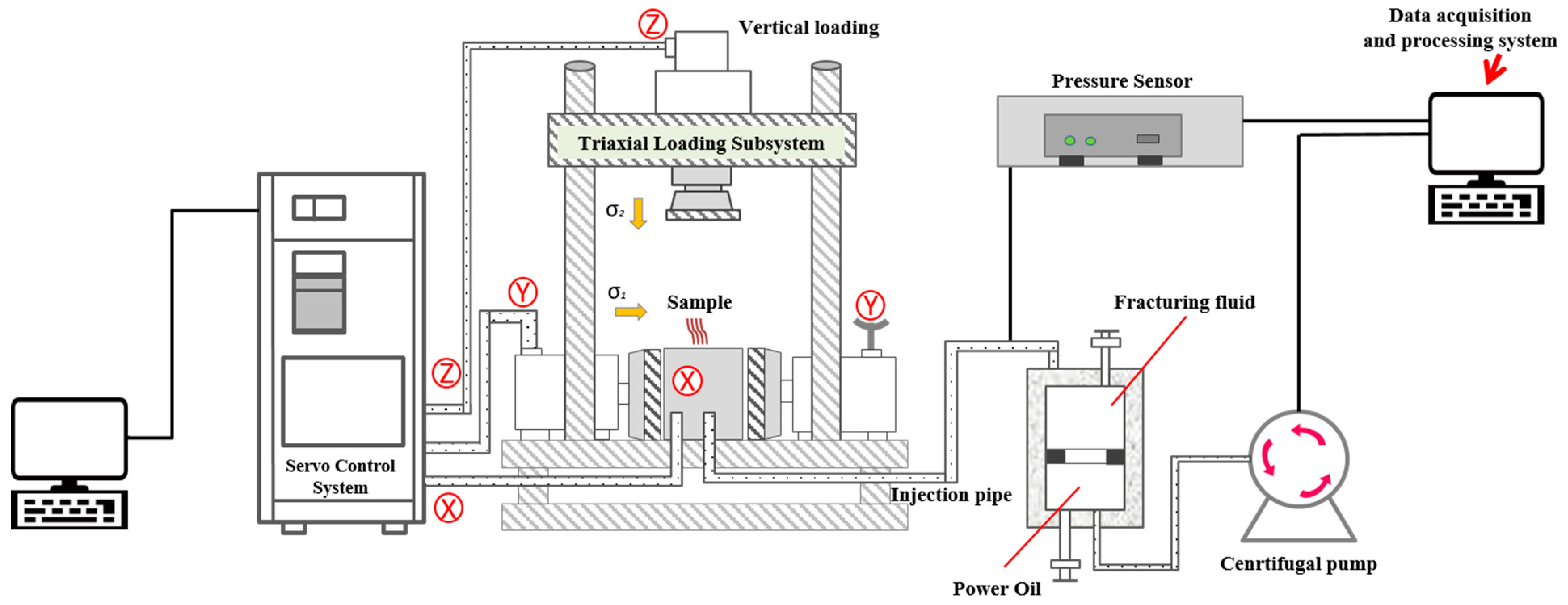
Hydraulic fracturing simulation device was used in the experiment (Figure 1). In the experiment, the pressure plate is pushed by an oil pressure pump set and a hydraulic cylinder to apply triaxial stress to rock samples in the core chamber. The maximum loading stress of X-axis is 10 MPa, and the maximum loading stress of Y-axis and Z-axis is 20 MPa. After the stress loading is completed, the piston pump is used to push the piston in the intermediate container to squeeze the fracturing fluid into the pipeline and enter the wellbore fracturing rock sample through the fluid injection pipeline. The maximum displacement of the piston pump is 1250 mL/min.
2.3. Experimental Design
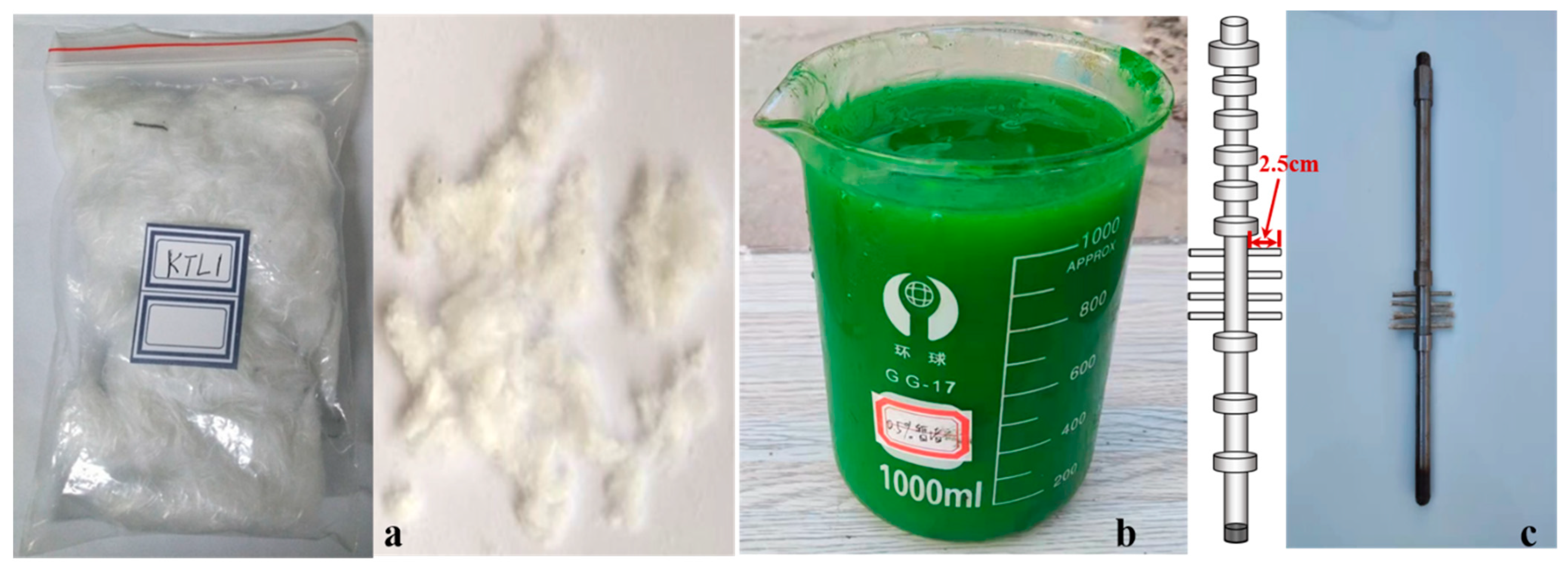
To analyze the effects of the completion method, fracturing method, and fracturing fluid displacement on the fracture propagating of a clayey silt hydrate reservoir, we designed the experimental scheme depicted in Table 3. Guar gum fracturing fluid is used as the fracturing fluid in conventional fracturing, and fiber fracturing fluid is used as the fracturing fluid in temporary plugging fracturing, as demonstrated in Figure 2a,b. Fiber fracturing fluid is prepared by using guar gum solution as the base fluid, adding fiber (fiber length: 6 cm) and cross-linking to form jelly. Figure 2c shows the wellbore for 4# and 5# samples with an initial perforation interval of 2.5 cm.
2.4. Experimental Procedure
- (1)
- Triaxial stress loading process
The sample was first placed in a triaxial stress loading chamber. To avoid the damage to the rock sample due to unbalanced loads in different directions, the stress in different directions was first applied at 1 MPa simultaneously in the experiment. Next, the vertical stress and the maximum horizontal stress continue to increase synchronously to 2 MPa, and then, the vertical stress gradually increases to 4 MPa. The specimen is stabilized under the boundary stress for 10 min to ensure the stress balance in the specimen. As the strength of the sample is much lower than that of conventional shale and sandstone samples, the stress is gradually applied at an interval of 0.5 MPa to avoid sample damage during confining pressure loading.
- (2)
- Fracturing process with guar gum fracturing fluid injection
The guar gum fracturing fluid is pumped into the sample using a centrifugal pump, and the change in pump pressure is recorded over time. The experiment is terminated when the injection pressure drops suddenly or fracturing fluid leakage is observed.
- (3)
- Fracturing process with fiber fracturing fluid injection
In the temporary plugging fracturing stage, a new fracturing fluid with a temporary plugging agent is pumped into the sample. The test is terminated when the injection pressure drops suddenly or the fracturing fluid leakage is observed.
- (4)
- Observation and recording of fracture morphology
After each test, the sample was removed from the true triaxial test frame. The sample was then split along induced fractures using a hammer and chisel to observe and record fracture morphology.
1#, 4#, and 5# samples shall be subject to conventional fracturing tests, and relevant tests shall be carried out according to steps (1), (2), and (4). 2# and 3# samples were subjected to the temporary plugging fracturing test, and relevant experiments were carried out according to steps (1), (2), (3), and (4).
3. Experimental Results and Analysis
3.1. Influence of Completion Scheme
Stimulated rock area (SRA) was utilized to quantitatively evaluate the effect of hydraulic fracturing [56]. SRA refers to the total induced fracture area in a sample after fracturing in the hydraulic fracturing simulation experiment. It is believed that the larger the SRA, the larger the area of the reservoir that the hydraulic fracture can communicate with after a reservoir reconstruction, and the better the effect of the increasing and stabilizing output. In the actual hydraulic fracturing simulation experiment, the area of the entire fracture plane is recorded as 1.00 (that is, close to 30 cm × 30 cm). In the actual calculation, the distribution area of the tracer on the fracture plane is divided into grades of 0.25, 0.50, and 0.75, respectively. After the test, the fractures on the surface of the sample were used to determine the fracture propagation direction. The approximate value of the fracture volume was then determined from the distribution pattern of the tracer. Finally, the complete fracture morphology is reconstructed using a drawing software.
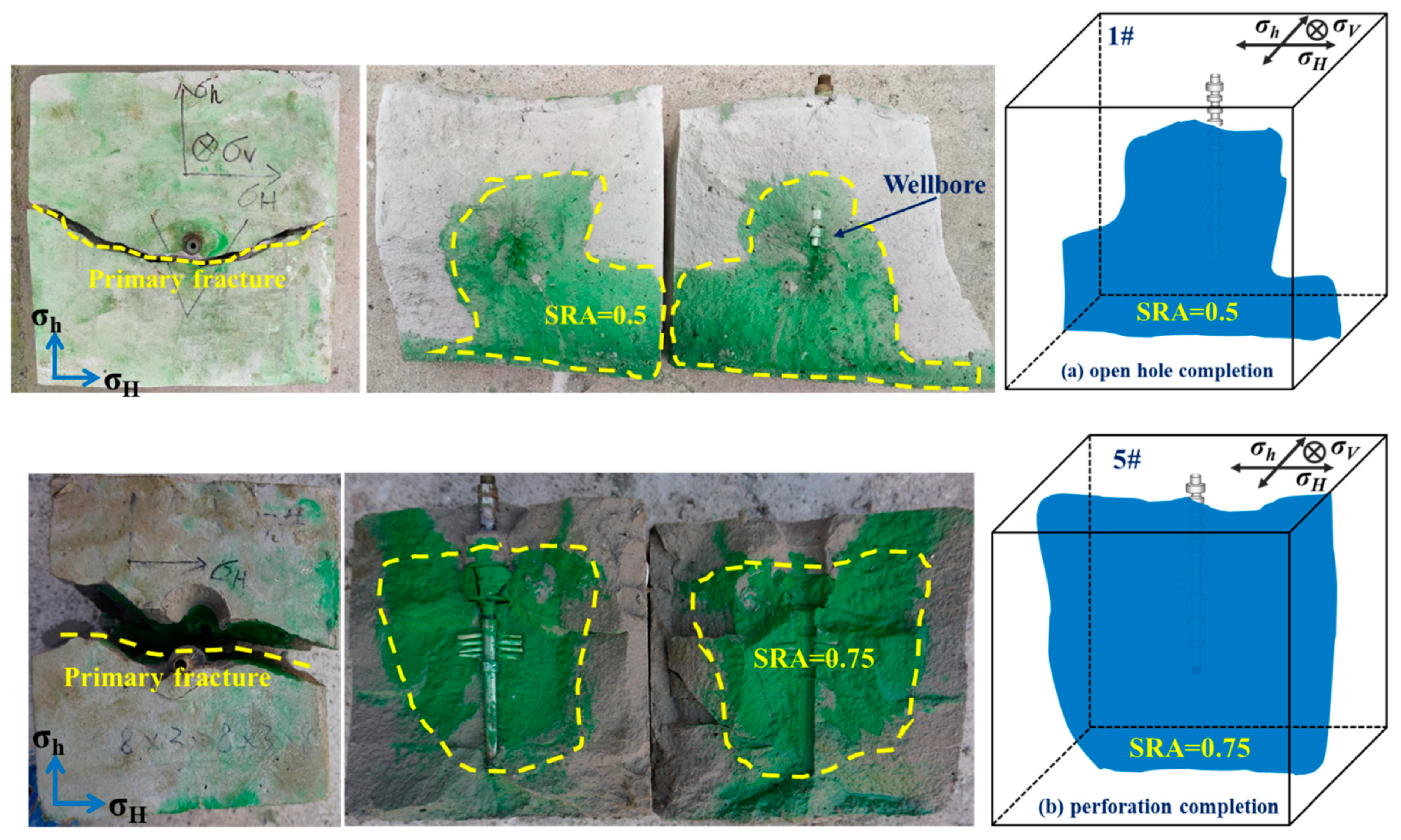
The purpose of 1# and 5# samples is to investigate the effect of the completion method on hydraulic fracture propagating and fracture geometry. The results demonstrated that the completion method has a significant impact on the SRA.
As shown in Figure 3, although the fracturing experiments of different completion methods finally formed approximately symmetrical double-wing vertical fractures, the fracture communication area (SRA = 0.75) produced by the perforated completion sample was significantly larger than that of the open hole completion sample (SRA = 0.5). At the same time, the breakdown pressure of the perforated completion sample was lower than that of the open hole completion sample. It was attributed to the prefabricated perforation section playing similar roles like micro-fractures and induced hydraulic fractures.
3.2. Impact of Fracturing Scheme
To evaluate the impact of fracturing mode on the hydraulic fracture propagation, the hydraulic fracturing experiment of 1# and 3# samples were conducted. The results suggested that the fracture morphology and the SRA are affected remarkably by the fracturing mode.
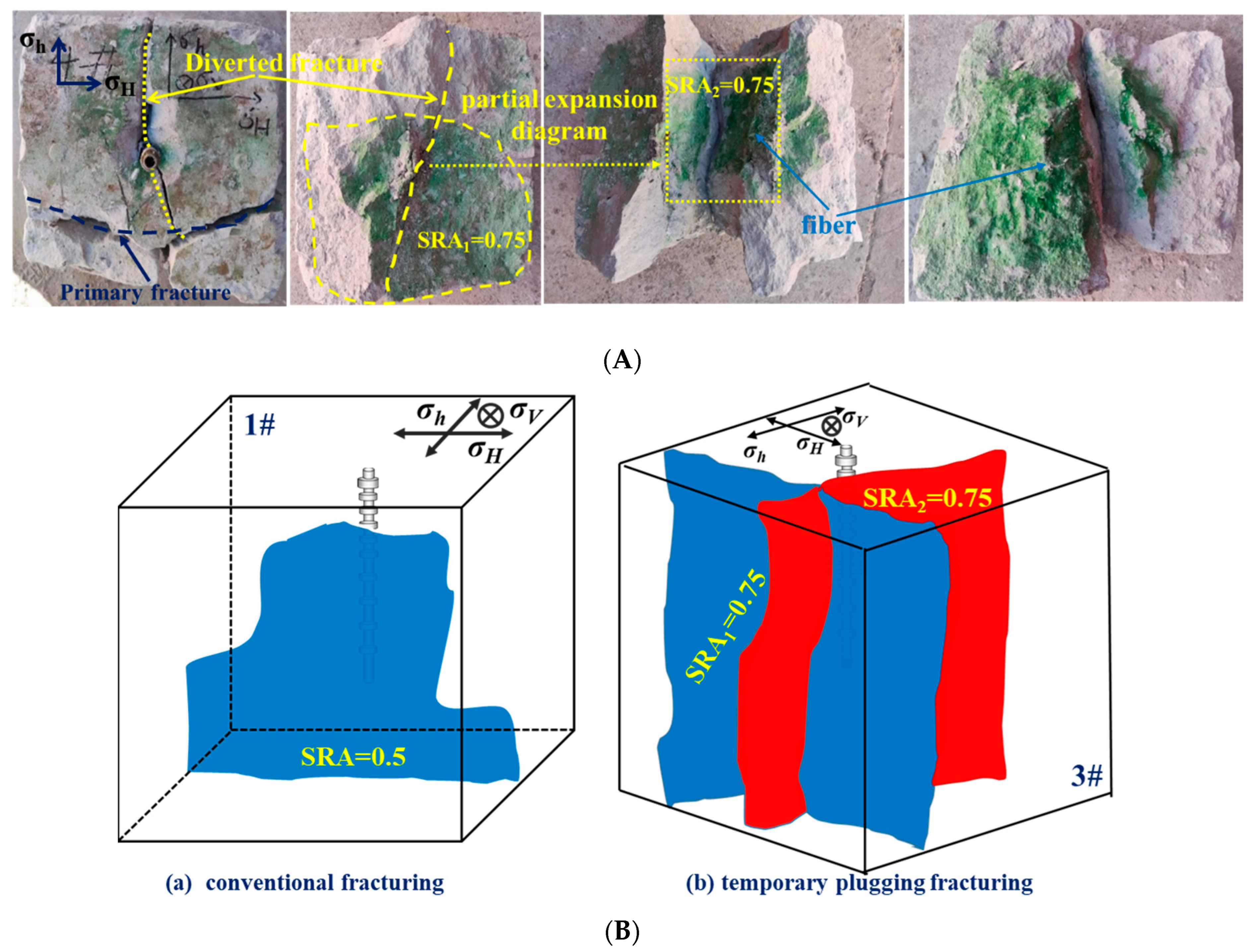
As depicted in Figure 4, a single vertical main fracture was formed in the conventional fracturing experiments. In the temporary plugging fracturing experiment, a vertical main fracture with an SRA of 0.75 was formed during the initial fracturing. In the subsequent temporary plugging fracturing, a diverting fracture with an angle of nearly 90° to the initial fracture was formed. Its fracture shape is obviously more complicated than that of the conventional fracturing. The SRA of the temporary plugging fracturing experiment (SRA = 1.5) is also significantly larger than that of the conventional fracturing (SRA = 0.5).
It should be pointed out that temporary plugging fracturing can increase the fracture complexity and significantly enhance the volume of reconstruction, but it requires a high treatment pressure, which is a problem. Meanwhile, it should be considered that the clayey silt hydrate reservoir is not diagenetic, its strength is low, and it can easily lose stability. Therefore, before a hydraulic fracturing construction, it is necessary to consider the reservoir conditions comprehensively, and fracturing in the layer with high hydrate saturation should be given priority.
3.3. Impact of Displacement
The objectives of 2# and 3# samples and 4# and 5# samples are to explore the impact of displacement on hydraulic fracture propagating and fracture geometry. The results indicated that the SRA was affected deeply by displacement.
As demonstrated in Figure 5B, although the complex fracture morphology of main fracture and steering fracture is formed in 2# and 3# samples after fracturing, the fracture morphology is analogous, but increasing the displacement can significantly improve the SRA. Owing to the increase in fracturing fluid displacement, the injection pressure and the pressure in the fracture would increase, and the stress at the fracture tip would increase, resulting in an increase in fracture propagation speed. Meanwhile, increasing the displacement increases the initiation pressure. This can be attributed to the high fracturing fluid displacement causing a high strain rate at the fracture tip, leading to an increase in the strength and initiation pressure of the hydrate sediments. Similar experimental phenomena are observed in the 4# and 5# samples. Although nearly symmetrical double wing vertical fractures are formed after fracturing, and the fracture morphology is similar, and increasing the displacement could significantly improve the SRA. Meanwhile, the increase in the displacement could lead to an increase in the fracture initiation pressure.
It is important to note that increasing the displacement can significantly increase the reconstruction volume, but in actual construction, a higher fracturing fluid displacement will increase the treatment pressure, thus improving the requirements for fracturing construction equipment. Meanwhile, considering that the clayey silt hydrate reservoir is not diagenetic, with a low strength and exhibiting an easy stability loss, the construction displacement must be reasonably optimized before conducting hydraulic fracturing.
3.4. Fracturing Pressure Curve
As depicted in Figure 6a, the breakdown pressure of 1#sample is obvious, about 11.78 MPa, and the propagation pressure curve is relatively stable, revealing the fracture geometry to be more regular. The result coincides with that of the single vertical fracture, which is observed by splitting the sample after the fracturing experiment (Figure 3). The breakdown pressure of 4# sample is obvious, about 7.53 MPa, and the propagation pressure is relatively stable, manifesting a more regular fracture geometry, but the breakdown pressure is significantly lower than that of 1# sample. This was due to the fact that the prefabricated perforation interval plays a similar role to that of microcracks. In addition, compared with 1# sample, 4# sample has a larger fluctuation after the breakdown point, which may be due to the difference in perforation initiation time. The pressure curve of the 5# sample resembles that of the 4# sample, but the breakdown pressure was higher than that of the 4#sample, which is 8.39 MPa.
The pressure curves of temporary plugging fracturing are illustrated in Figure 7. In the fracturing process (q1) of 2# sample pump injection without a temporary plugging agent fracturing fluid, there are obvious breakdown points, high fracture initiation pressure, and low fracture propagation pressure, and this is similar to the pressure change law in the conventional fracturing process. After pumping the fracturing fluid with a fiber temporary plugging agent (q2), the treatment pressure gradually increases to 22.9 MPa, and the pressure fluctuation is obvious. The pressure characteristics are caused by the temporary plugging agent migrating into the fracture and compressing the new fracture. From the pressure curve, the pressure rises and then falls many times, and each such process can be regarded as a quasi-rupture process. As the fiber fracturing fluid is injected into the wellbore, the fluid is filtered along the formed fracture, and the fiber slowly accumulates at the beginning of the fracture, thereby creating a filter cake. When the filter cake reaches a certain level, the rate of fluid filtration slows down, or the liquid can no longer enter the fracture, causing a pressure rise. After the pressure has risen to a certain level, due to the formation of new fractures or the propagation of old fractures, the fluid is filtered into the sample again, resulting in a rapid drop in pressure. When the new filter loss reaches a certain extent, the fiber gathers again to form a filter cake, resulting in a new round of pressure rise, and the injection pressure decreases again after the new fracture or the old fracture propagates, and this process is repeated. The fracturing curve of 3# sample is similar. The main difference is that the fluctuation is more obvious after pumping the fracturing fluid with a fiber temporary plugging agent. The phenomenon indicates that many new fractures are generated during the fracturing process, and the fracture area of 3# sample is also significantly larger than that of 2# sample.
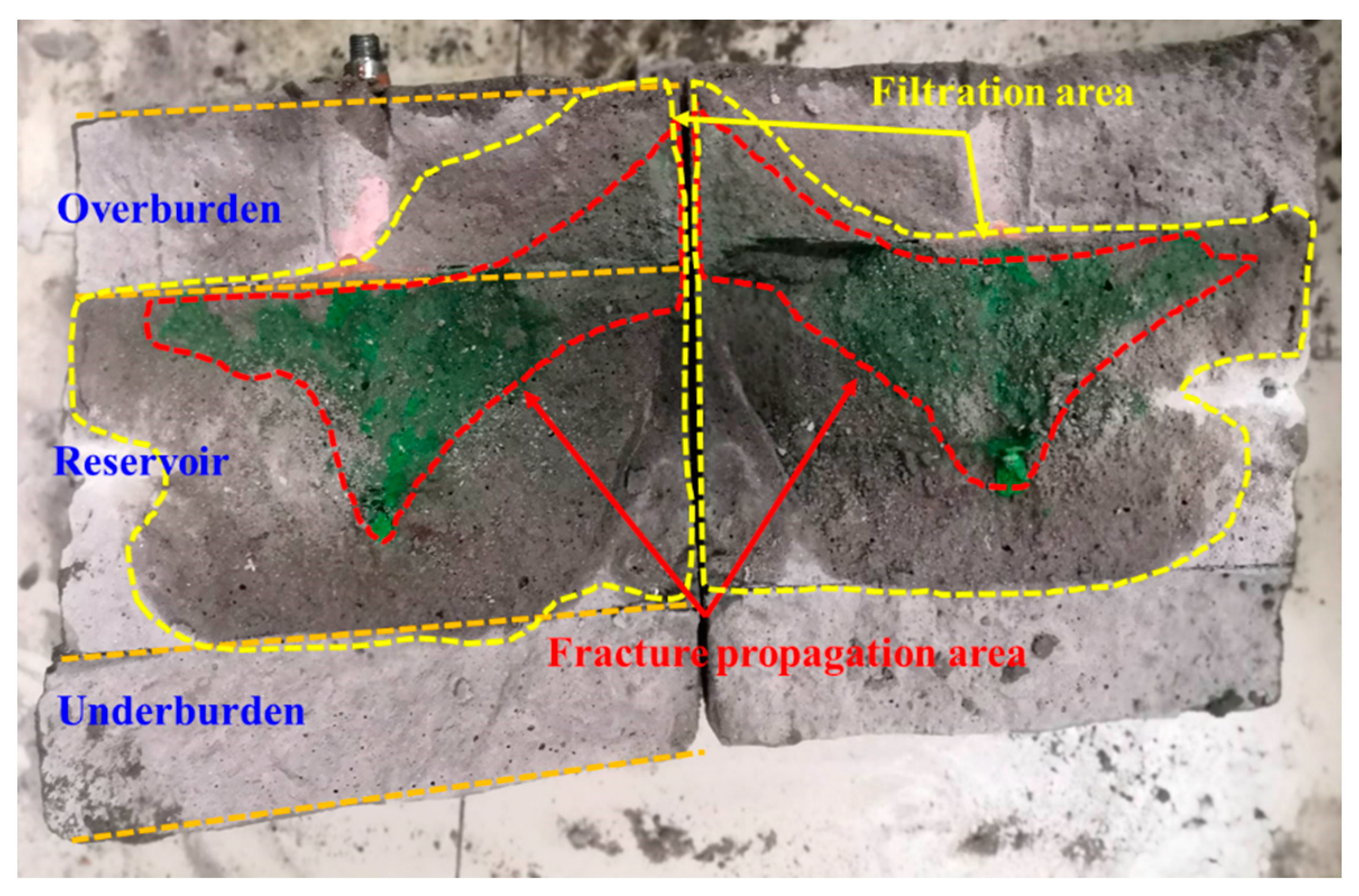
3.5. Analysis of Filtration Area and Fracture Propagation Area
Fracture propagation area and fracturing fluid filtration area are be observed in the fracturing physical simulation experiment. The Figure 8 shows the distribution of fracture propagation area and fracturing fluid filtration area of 4# and 5# samples after fracturing. It can be found that the fracturing fluid filtrate area is significantly larger than the fracture propagation area under both low and high displacement conditions. Compared with tight sandstone reservoir samples [57], the difference between fracturing fluid filtration area and fracture propagation area is greater, as shown in Figure 9. The filtration area of fracturing fluid is obviously larger than the fracture propagation area. Fracturing fluid can form a large range of filtration area quickly, which may be due to the high argillaceous content of clayey silt hydrate reservoirs. However, in the actual hydraulic fracturing treatment, we should avoid the formation of a large range of filtration area, which is a waste of fracturing fluid and fracturing fluid energy. Therefore, when performing the hydraulic fracturing in clayey silt hydrate reservoirs, high-viscosity fracturing fluids should be used to reduce the fracturing fluid filtration and increase the fracturing fluid efficiency.
4. Conclusions
Based on a series of large-size (30 × 30 × 30 cm) laboratory physical simulation experiments, the effects of the completion method, fracturing method, and fracturing fluid displacement on the hydraulic fracture propagation behavior of clayey silt hydrate-bearing sediments were studied. The drawn conclusions are as follows:
(1) Compared with the open hole completion, the perforated completion can result in a significant increase in the fracture reconstruction area and a reduction in the fracture initiation pressure. As the clayey silt hydrate reservoir is not diagenetic and has a low strength, the perforated completion has obvious advantages. It is recommended to use the perforated completion in the fracturing of this type of reservoir.
(2) Due to the small horizontal stress difference, the temporary plugging fracturing is feasible in clayey silt hydrate reservoirs. Temporary plugging fracturing can form steering fractures and significantly improve fracture complexity and fracture area.
(3) The fracture area is significantly increased with the increase in fracturing fluid displacement, but a higher fracturing fluid displacement will improve the treatment pressure, thus increasing the requirements of fracturing construction equipment. Meanwhile, considering that the clayey silt hydrate reservoir is not diagenetic, its strength is low, and it can easily lose stability, the displacement needs to be reasonably optimized before fracturing.
(4) When conducting the fracturing construction in a clayey silt hydrate reservoir, the fracturing fluid filtration area obviously exceeds the fracture propagation area. Therefore, a high-viscosity fracturing fluid should be selected to reduce the filtration and improve the fracturing fluid efficiency.
(5) It should be pointed out that, in our research, we only considered the similarity of the mechanical properties and porosity and permeability properties between the simulated samples and the actual reservoir conditions. However, the actual fracturing of the NGH reservoir also involves the decomposition and phase transformation of the hydrate. Hydrate dissociation may lead to a rapid increase in pore pressure, and it also reduces the hydrate formation. The change in formation characteristics will result in the change in reservoir porosity and permeability. Those changes have an important impact on the safety and fracture propagation behavior of the hydraulic fracturing construction. Therefore, it is necessary to focus on this aspect in the future research.
Author Contributions
Methodology, Y.Y. and H.Z.; Investigation, K.S. All authors have read and agreed to the published version of the manuscript.
Funding
This work is supported by the National Natural Science Foundation of China (grant no. 51991364) and the Basic and Applied Basic Research Foundation of Guangdong Province, China (No.2020B0301030003). The authors gratefully appreciate their support.
Data Availability Statement
Data are contained within the article.
Conflicts of Interest
The authors declare no conflict of interest.
Nomenclature
| NGH | natural gas hydrate |
| THF | Tetrahydrofuran |
| SRA | stimulated rock area |
| GMGS | Guangzhou Marine Geological Survey |
References
- Sloan, E.D. Fundamental principles and applications of natural gas hydrates. Nature 2003, 426, 353–359. [Google Scholar] [CrossRef]
- Ruppel, C.D.; Kessler, J.D. The interaction of climate change and methane hydrates. Rev. Geophys. 2017, 55, 126–168. [Google Scholar] [CrossRef]
- Management, M.M.J.E. Natural Gas Hydrate: In Oceanic and Permafrost Environments; Springer: Berlin/Heidelberg, Germany, 2003. [Google Scholar]
- Kerr, R.A. Energy-Gas hydrate resource: Smaller but sooner. Science 2004, 303, 946–947. [Google Scholar] [CrossRef]
- Milkov, A.V. Global estimates of hydrate-bound gas in marine sediments: How much is really out there? Earth-Sci. Rev. 2004, 66, 183–197. [Google Scholar] [CrossRef]
- Yang, M.; Zhe, F.; Zhao, Y.; Jiang, L.; Zhao, J.; Song, Y. Effect of depressurization pressure on methane recovery from hydrate–gas–water bearing sediments. Fuel 2016, 166, 419–426. [Google Scholar] [CrossRef]
- Tupsakhare, S.S.; Kattekola, S.; Castaldi, M.J. An Application of the Results from the Large-Scale Thermal Stimulation Method of Methane Hydrate Dissociation to the Field Tests. Ind. Eng. Chem. Res. 2017, 56, 4588–4599. [Google Scholar] [CrossRef]
- Li, G.; Li, X.-S.; Tang, L.-G.; Zhang, Y. Experimental investigation of production behavior of methane hydrate under ethylene glycol injection in unconsolidated sediment. Energy Fuels 2007, 21, 3388–3393. [Google Scholar] [CrossRef]
- Koh, D.-Y.; Kang, H.; Lee, J.-W.; Park, Y.; Kim, S.-J.; Lee, J.; Lee, J.Y.; Lee, H. Energy-efficient natural gas hydrate production using gas exchange. Appl. Energy 2016, 162, 114–130. [Google Scholar] [CrossRef]
- Ma, S.; Zheng, J.-N.; Zhao, J.; Yang, M.; Song, Y. Experimental analysis on thermodynamic stability and methane leakage during solid fluidization process of methane hydrate. Fuel 2021, 284, 119020. [Google Scholar] [CrossRef]
- Nair, V.C.; Prasad, S.K.; Kumar, R.; Sangwai, J.S. Energy recovery from simulated clayey gas hydrate reservoir using depressurization by constant rate gas release, thermal stimulation and their combinations. Appl. Energy 2018, 225, 755–768. [Google Scholar] [CrossRef]
- Feng, Y.; Chen, L.; Suzuki, A.; Kogawa, T.; Okajima, J.; Komiya, A.; Maruyama, S. Enhancement of gas production from methane hydrate reservoirs by the combination of hydraulic fracturing and depressurization method. Energy Convers. Manag. 2019, 184, 194–204. [Google Scholar] [CrossRef]
- Zhao, J.; Zhang, L.; Chen, X.; Zhang, Y.; Liu, Y.; Song, Y. Combined replacement and depressurization methane hydrate recovery method. Energy Explor. Exploit. 2016, 34, 129–139. [Google Scholar] [CrossRef]
- Jin, G.; Xu, T.; Xin, X.; Wei, M.; Liu, C. Numerical evaluation of the methane production from unconfined gas hydrate-bearing sediment by thermal stimulation and depressurization in Shenhu area, South China Sea. J. Nat. Gas Sci. Eng. 2016, 33, 497–508. [Google Scholar] [CrossRef]
- Yu, T.; Guan, G.; Abudula, A.; Yoshida, A.; Wang, D.; Song, Y. Gas recovery enhancement from methane hydrate reservoir in the Nankai Trough using vertical wells. Energy 2019, 166, 834–844. [Google Scholar] [CrossRef]
- Boswell, R.; Collett, T.S. Current perspectives on gas hydrate resources. Energy Environ. Sci. 2011, 4, 1206–1215. [Google Scholar] [CrossRef]
- You, K.; Flemings, P.B.; Malinverno, A.; Collett, T.S.; Darnell, K. Mechanisms of Methane Hydrate Formation in Geological Systems. Rev. Geophys. 2019, 57, 1146–1196. [Google Scholar] [CrossRef]
- Sun, J.; Ning, F.; Zhang, L.; Liu, T.; Peng, L.; Liu, Z.; Li, C.; Jiang, G. Numerical simulation on gas production from hydrate reservoir at the 1st offshore test site in the eastern Nankai Trough. J. Nat. Gas Sci. Eng. 2016, 30, 64–76. [Google Scholar] [CrossRef]
- Anderson, B.; Hancock, S.; Wilson, S.; Enger, C.; Collett, T.; Boswell, R.; Hunter, R. Formation pressure testing at the Mount Elbert Gas Hydrate Stratigraphic Test Well, Alaska North Slope: Operational summary, history matching, and interpretations. Mar. Pet. Geol. 2011, 28, 478–492. [Google Scholar] [CrossRef]
- Qin, X.-W.; Lu, J.-A.; Lu, H.-L.; Qiu, H.-J.; Liang, J.-Q.; Kang, D.-J.; Zhan, L.-S.; Lu, H.-F.; Kuang, Z.-G. Coexistence of natural gas hydrate, free gas and water in the gas hydrate system in the Shenhu Area, South China Sea-ScienceDirect. China Geol. 2020, 3, 210–220. [Google Scholar] [CrossRef]
- Liu, C.; Shen, Y.; Zhang, J.; Lu, D.; Liu, H.; Wu, H. Production analysis in shale gas reservoirs based on fracturing-enhanced permeability areas. Sci. China-Phys. Mech. Astron. 2019, 62, 104611. [Google Scholar] [CrossRef]
- Tan, Y.; Pan, Z.; Feng, X.-T.; Zhang, D.; Connell, L.D.; Li, S. Laboratory characterisation of fracture compressibility for coal and shale gas reservoir rocks: A review. Int. J. Coal Geol. 2019, 204, 1–17. [Google Scholar] [CrossRef]
- Zhang, R.-H.; Zhang, L.-H.; Tang, H.-Y.; Chen, S.-N.; Zhao, Y.-L.; Wu, J.-F.; Wang, K.-R. A simulator for production prediction of multistage fractured horizontal well in shale gas reservoir considering complex fracture geometry. J. Nat. Gas Sci. Eng. 2019, 67, 14–29. [Google Scholar] [CrossRef]
- Ma, X.; Jiang, D.; Fang, X.; Wang, X. Numerical simulation of single-cluster and multi-cluster fracturing of hydrate reservoir based on cohesive element. Eng. Fract. Mech. 2022, 265, 108365. [Google Scholar] [CrossRef]
- Yu, Y.; Liu, J.; Li, B.; Sun, Y. Analysis of the hydraulic fracturing mechanism and fracture propagation law with a new extended finite element model for the silty hydrate reservoir in the South China Sea. J. Nat. Gas Sci. Eng. 2022, 101, 104535. [Google Scholar] [CrossRef]
- Ma, X.; Cheng, J.; Sun, Y.; Li, S. 2D Numerical Simulation of Hydraulic Fracturing in Hydrate-Bearing Sediments Based on the Cohesive Element. Energy Fuels 2021, 35, 3825–3840. [Google Scholar] [CrossRef]
- Liu, X.; Sun, Y.; Guo, T.; Rabiei, M.; Qu, Z.; Hou, J. Numerical simulations of hydraulic fracturing in methane hydrate reservoirs based on the coupled thermo-hydrologic-mechanical-damage (THMD) model. Energy 2022, 238, 122054. [Google Scholar] [CrossRef]
- Chen, C.; Yang, L.; Jia, R.; Sun, Y.; Guo, W.; Chen, Y.; Li, X. Simulation Study on the Effect of Fracturing Technology on the Production Efficiency of Natural Gas Hydrate. Energies 2017, 10, 1241. [Google Scholar] [CrossRef]
- Yang, L.; Chen, C.; Jia, R.; Sun, Y.; Guo, W.; Pan, D.; Li, X.; Chen, Y. Influence of Reservoir Stimulation on Marine Gas Hydrate Conversion Efficiency in Different Accumulation Conditions. Energies 2018, 11, 339. [Google Scholar] [CrossRef]
- Sun, J.; Ning, F.; Liu, T.; Liu, C.; Chen, Q.; Li, Y.; Cao, X.; Mao, P.; Zhang, L.; Jiang, G. Gas production from a silty hydrate reservoir in the South China Sea using hydraulic fracturing: A numerical simulation. Energy Sci. Eng. 2019, 7, 1106–1122. [Google Scholar] [CrossRef]
- Shan, L.; Fu, C.; Liu, Y.; Qi, Y. A feasibility study of using frac-packed wells to produce natural gas from subsea gas hydrate resources. Energy Sci. Eng. 2020, 8, 1247–1259. [Google Scholar] [CrossRef]
- Ye, J.; Qin, X.; Xie, W.; Lu, H.; Ma, B.; Qiu, H.; Liang, J.; Lu, J.; Kuang, Z.; Lu, C.; et al. Main progress of the second gas hydrate trial production in the South China Sea. Geol. China 2020, 47, 557–568. [Google Scholar]
- Too, J.L.; Cheng, A.; Khoo, B.C.; Palmer, A.; Linga, P. Hydraulic fracturing in a penny-shaped crack. Part II: Testing the frackability of methane hydrate-bearing sand. J. Nat. Gas Sci. Eng. 2018, 52, 619–628. [Google Scholar] [CrossRef]
- Liu, X.; Zhang, W.; Qu, Z.; Guo, T.; Sun, Y.; Rabiei, M.; Cao, Q. Feasibility evaluation of hydraulic fracturing in hydrate-bearing sediments based on analytic hierarchy process-entropy method (AHP-EM). J. Nat. Gas Sci. Eng. 2020, 81, 103434. [Google Scholar] [CrossRef]
- Ito, T.; Igarashi, A.; Suzuki, K.; Nagakubo, S.; Matsuzawa, M.; Yamamoto, K. Laboratory Study of Hydraulic Fracturing Behavior in Unconsolidated Sands for Methane Hydrate Production. In Proceedings of the Offshore Technology Conference, Houston, TX, USA, 5–8 May 2008. [Google Scholar]
- Konno, Y.; Jin, Y.; Yoneda, J.; Uchiumi, T.; Shinjou, K.; Nagao, J. Hydraulic fracturing in methane-hydrate-bearing sand. Rsc Adv. 2016, 6, 73148–73155. [Google Scholar] [CrossRef]
- Zhang, W.; Shi, X.; Jiang, S.; Cao, Q.; Wang, F.; Wang, Z.; Ge, Y.; Du, Y. Experimental study of hydraulic fracture initiation and propagation in highly saturated methane-hydrate-bearing sands. J. Nat. Gas Sci. Eng. 2020, 79, 73148–73155. [Google Scholar] [CrossRef]
- Yao, Y.; Guo, Z.; Zeng, J.; Li, D.; Lu, J.; Liang, D.; Jiang, M. Discrete Element Analysis of Hydraulic Fracturing of Methane Hydrate-Bearing Sediments. Energy Fuels 2021, 35, 6644–6657. [Google Scholar] [CrossRef]
- Yu, Y.; Liu, J.; Ma, X.; Yang, G.; Sun, Y.; Sun, W.; Shi, W. Mechanism Analysis of Multi-Cluster Fracture Interference in Horizontal Wells of Hydrate Reservoirs in the South China Sea. Energy Fuels 2022, 36, 3580–3595. [Google Scholar] [CrossRef]
- Lu, C.; Qin, X.; Mao, W.; Ma, C.; Geng, L.; Yu, L.; Bian, H.; Meng, F.; Qi, R. Experimental Study on the Propagation Characteristics of Hydraulic Fracture in Clayey-Silt Sediments. Geofluids 2021, 2021, 6698649. [Google Scholar] [CrossRef]
- Sun, Y.; Li, S.; Ma, X.; Jiang, D. Experimental study on hydraulic fracturing behavior of frozen clayey silt and hydrate-bearing clayey silt. Fuel 2022, 322, 124366. [Google Scholar]
- Zhang, R.; Hou, B.; Tan, P.; Muhadasi, Y.; Fu, W.; Dong, X.; Chen, M. Hydraulic fracture propagation behavior and diversion characteristic in shale formation by temporary plugging fracturing. J. Pet. Sci. Eng. 2020, 190, 107063. [Google Scholar] [CrossRef]
- Tan, P.; Jin, Y.; Han, K.; Hou, B.; Chen, M.; Guo, X.; Gao, J.J.F. Analysis of hydraulic fracture initiation and vertical propagation behavior in laminated shale formation. Fuel 2017, 206, 482–493. [Google Scholar] [CrossRef]
- Zhao, H.; Wang, X.; Liu, Z. Experimental investigation of hydraulic sand fracturing on fracture propagation under the influence of coal macrolithotypes in Hancheng block, China. J. Pet. Sci. Eng. 2019, 175, 60–71. [Google Scholar] [CrossRef]
- Lee, J.; Lee, D.; Seo, Y. Experimental investigation of the exact role of large-molecule guest substances (LMGSs) in determining phase equilibria and structures of natural gas hydrates. Energy 2021, 215, 119219. [Google Scholar] [CrossRef]
- Iida, T.; Mori, H.; Mochizuki, T.; Mori, Y.H. Formation and dissociation of clathrate hydrate in stoichiometric tetrahydrofuran-water mixture subjected to one-dimensional cooling or heating. Chem. Eng. Sci. 2001, 56, 4747–4758. [Google Scholar] [CrossRef]
- Nie, S.; Zhong, X.; Song, J.; Tu, G.; Chen, C. Engineering, Experimental study on hydraulic fracturing in clayey-silty hydrate-bearing sediments and fracability evaluation based on multilayer perceptron-analytic hierarchy process. J. Nat. Gas Sci. Eng. 2022, 106, 104735. [Google Scholar] [CrossRef]
- Waite, W.F.; Santamarina, J.C.; Cortes, D.D.; Dugan, B.; Espinoza, D.N.; Germaine, J.; Jang, J.; Jung, J.W.; Kneafsey, T.J.; Shin, H.; et al. Physical Properties of Hydrate-Bearing Sediments. Rev. Geophys. 2009, 47. [Google Scholar] [CrossRef]
- Zhang, H.Q.; Yang, S.X.; Wu, N.Y.; Su, X.; Gary, H. Successful and surprising results for China’s first gas hydrate drilling expedition. Fire Ice Fall 2007, 7, 6–9. [Google Scholar]
- Nengyou, W.U.; Haiqi, Z.; Shengxiong, Y.; Jinqiang, L.; Hongbin, W. Preliminary Discussion on Natural Gas Hydrate (NGH) Reservoir System of Shenhu Area, North Slope of South China Sea. Nat. Gas Ind. 2007, 27, 1–6. [Google Scholar]
- Su, Z.; Moridis, G.J.; Zhang, K.; Wu, N. A huff-and-puff production of gas hydrate deposits in Shenhu area of South China Sea through a vertical well. J. Pet. Sci. Eng. 2012, 86–87, 54–61. [Google Scholar] [CrossRef]
- Su, M.; Luo, K.; Fang, Y.; Kuang, Z.; Yang, C.; Liang, J.; Liang, C.; Chen, H.; Lin, Z.; Wang, C.; et al. Grain-size characteristics of fine-grained sediments and association with gas hydrate saturation in Shenhu Area, northern South China Sea. Ore Geol. Rev. 2021, 129, 103889. [Google Scholar] [CrossRef]
- Lu, H.; Chen, H.; Chen, F.; Liao, Z.J. Mineralogy of the sediments from gas-hydrate drilling sites, Shenhu area, South China Sea. Geol. Res. S. China Sea 2009, 28–39. [Google Scholar]
- Yun, T.S.; Santamarina, J.C.; Ruppel, C. Mechanical properties of sand, silt, and clay containing tetrahydrofuran hydrate. J. Geophys. Res. 2007, 112. [Google Scholar] [CrossRef]
- Ning, F.; Wu, N.; Li, S.; Zhang, K.; Yu, Y.; Liu, L.; Sun, J.; Guosheng, J.; Sun, C.; Chen, G. Estimation of in-situ mechanical properties of gas hydrate-bearing sediments from well logging. Pet. Explor. Dev. 2013, 40, 542–547. [Google Scholar] [CrossRef]
- Hou, B.; Chen, M.; Li, Z.; Wang, Y.; Diao, C. Propagation area evaluation of hydraulic fracture networks in shale gas reservoirs. Pet. Explor. Dev. 2014, 41, 833–838. [Google Scholar] [CrossRef]
- Zhao, H.; Xiong, Y.; Zhen, H.; Liu, C.; Li, X. Experimental investigation on the fracture propagation of three-stage acid fracturing of tight sandstone gas reservoir. J. Pet. Sci. Eng. 2022, 211, 110143. [Google Scholar] [CrossRef]
Figure 1.
True triaxial hydraulic fracturing system.

Figure 2.
Diagram of fiber fracturing fluid and wellbore: (a) fiber used for configuring fiber fracturing fluid; (b) fiber fracturing fluid with tracer added; and (c) wellbore in perforated mode.
Figure 2.
Diagram of fiber fracturing fluid and wellbore: (a) fiber used for configuring fiber fracturing fluid; (b) fiber fracturing fluid with tracer added; and (c) wellbore in perforated mode.

Figure 3.
Fracture morphology comparison between open hole completion and perforation completion: (a) open hole completion (1#) and (b) perforation completion (5#).
Figure 3.
Fracture morphology comparison between open hole completion and perforation completion: (a) open hole completion (1#) and (b) perforation completion (5#).

Figure 4.
Fracture morphology comparison between conventional fracturing and temporary plugging fracturing: (A) fracture morphology after hydraulic fracturing (3#) and (B) fracture reconstruction diagram after hydraulic fracturing (1# and 3# samples).
Figure 4.
Fracture morphology comparison between conventional fracturing and temporary plugging fracturing: (A) fracture morphology after hydraulic fracturing (3#) and (B) fracture reconstruction diagram after hydraulic fracturing (1# and 3# samples).

Figure 5.
Fracture morphology comparison between low and high displacements: (A) fracture morphology after hydraulic fracturing (2#), (B) fracture reconstruction diagram after hydraulic fracturing (2# and 3# samples), (C) fracture morphology after hydraulic fracturing (4#), and (D) fracture reconstruction diagram after hydraulic fracturing (4# and 5# samples).


Figure 6.
Pressure curves of conventional fracturing. (a) 1#; (b) 4# and 5#.

Figure 7.
Pressure curves of temporary plugging fracturing.

Figure 8.
The distribution of filtration area and fracture propagation area after fracturing.

Figure 9.
The distribution of filtration area and fracture propagation area after fracturing of tight sandstone sample (Orange dashed Lines representing the boundary between reservoirs and interlayer).
Figure 9.
The distribution of filtration area and fracture propagation area after fracturing of tight sandstone sample (Orange dashed Lines representing the boundary between reservoirs and interlayer).


Table 1.
The mineralogical components of clayey-silty sediments.
| Grain Size (μm) | Actual Mass Proportion (%) | Average Value (%) | Experimental Mass Proportion (%) |
|---|---|---|---|
| Clay: <4 | 15–45 | -- | 21 |
| Silt: 4–63 | 50–80 | -- | 75 |
| Sand: >63 | <5 | -- | 4 |
| Clay minerals at SH2 site | 11–27 | 19.64 | 21 |
| Montmorillonite | 33–59 | 47.04 | 45 |
| Illite | 22–39 | 29.28 | 30 |
| Chlorite | 9–17 | 13.17 | 15 |
| Kaolinite | 7–14 | 10.51 | 10 |
Table 2.
The porosity, permeability, and mechanical parameters of the simulated samples.
| Specimen Number | Elastic Modulus (MPa) | Poisson’s Ratio | Compressive Strength (MPa) | Tensile Strength (MPa) | Porosity (%) | Permeability (mD) |
|---|---|---|---|---|---|---|
| 1 | 391.35 | 0.29 | 3.36 | 0.31 | 36.4 | 2.39 |
| 2 | 399.15 | 0.30 | 3.63 | 0.33 | 32.3 | 2.76 |
| 3 | 387.54 | 0.31 | 2.99 | 0.27 | 36.6 | 2.97 |
| 4 | 386.62 | 0.32 | 2.8 | 0.26 | 39.6 | 3.05 |
| 5 | 396.46 | 0.33 | 3.41 | 0.31 | 34.5 | 2.66 |
Table 3.
Summary of experimental parameters.
| Sample Number | Completion Method | Fracturing Method | (σv/σH/σh (MPa)) | Displacement (mL/min) | Fluid Viscosity (mPa·s) |
|---|---|---|---|---|---|
| 1# | open hole completion | conventional fracturing | 4/2/1 | 100 | 100 |
| 2# | temporary plugging fracturing | 50 | 100 | ||
| 3# | temporary plugging fracturing | 100 | |||
| 4# | perforated completion | conventional fracturing | 50 | 100 | |
| 5# | conventional fracturing | 100 |
Disclaimer/Publisher’s Note: The statements, opinions and data contained in all publications are solely those of the individual author(s) and contributor(s) and not of MDPI and/or the editor(s). MDPI and/or the editor(s) disclaim responsibility for any injury to people or property resulting from any ideas, methods, instructions or products referred to in the content. |
© 2024 by the authors. Licensee MDPI, Basel, Switzerland. This article is an open access article distributed under the terms and conditions of the Creative Commons Attribution (CC BY) license (https://creativecommons.org/licenses/by/4.0/).
Share and Cite
MDPI and ACS Style
Yu, Y.; Shen, K.; Zhao, H. Experimental Investigation of Fracture Propagation in Clayey Silt Hydrate-Bearing Sediments. Energies 2024, 17, 528. https://doi.org/10.3390/en17020528
AMA Style
Yu Y, Shen K, Zhao H. Experimental Investigation of Fracture Propagation in Clayey Silt Hydrate-Bearing Sediments. Energies. 2024; 17(2):528. https://doi.org/10.3390/en17020528
Chicago/Turabian StyleYu, Yanjiang, Kaixiang Shen, and Haifeng Zhao. 2024. "Experimental Investigation of Fracture Propagation in Clayey Silt Hydrate-Bearing Sediments" Energies 17, no. 2: 528. https://doi.org/10.3390/en17020528
Note that from the first issue of 2016, this journal uses article numbers instead of page numbers. See further details here.