
Dual-Mode Conical Horn Antenna with 2-D Azimuthal Monopulse Pattern for Millimeter-Wave Applications †

 , , ,
, , ,
Abstract
:1. Introduction
2. Design of the Mode Converters for the Sum and Difference Patterns
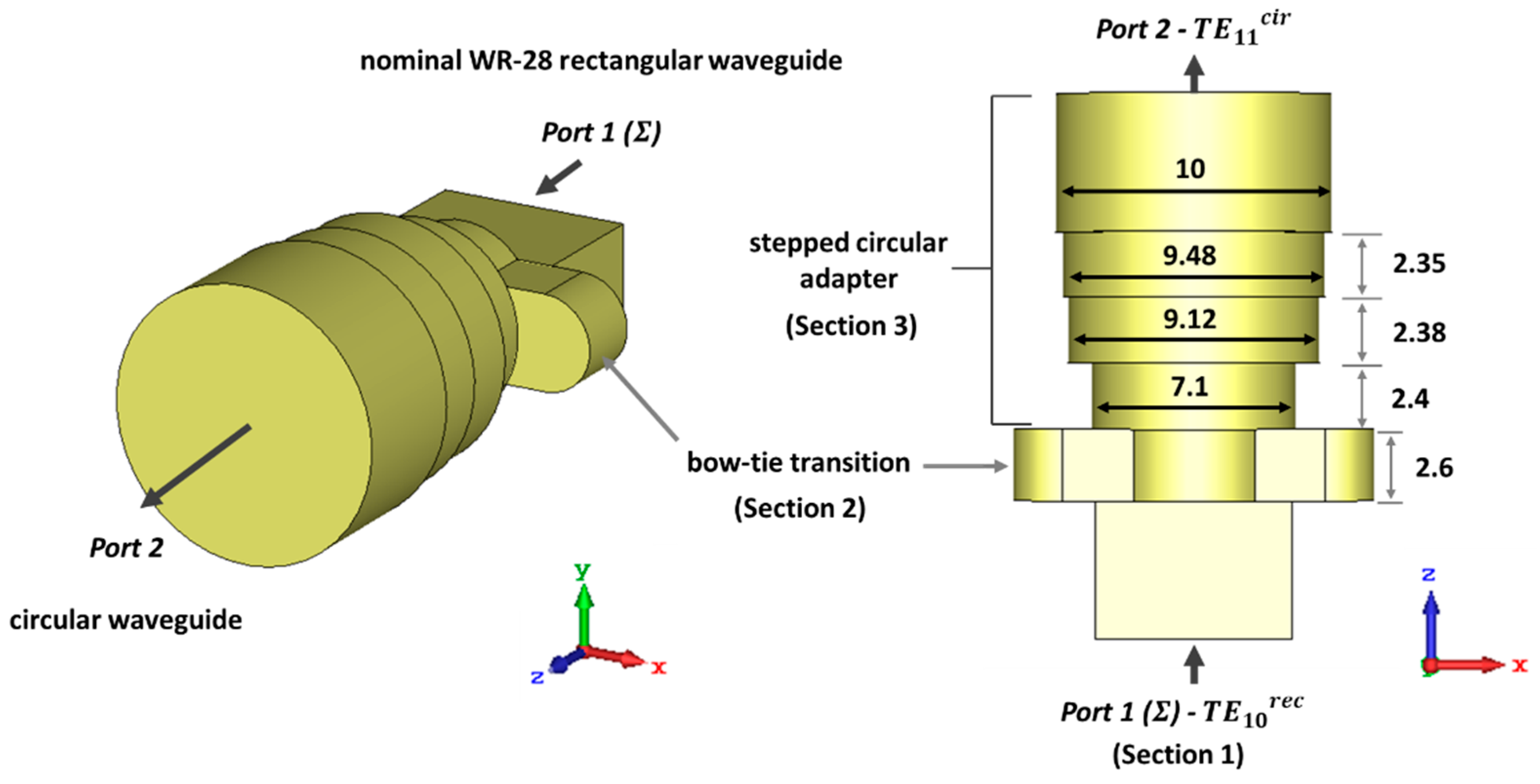
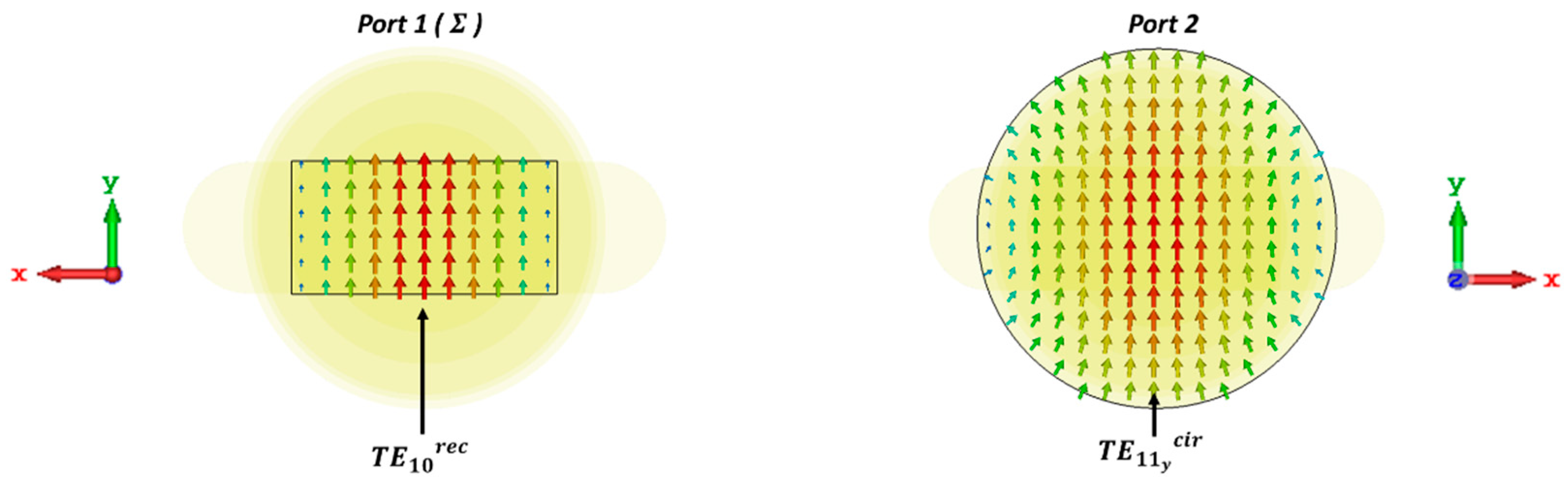
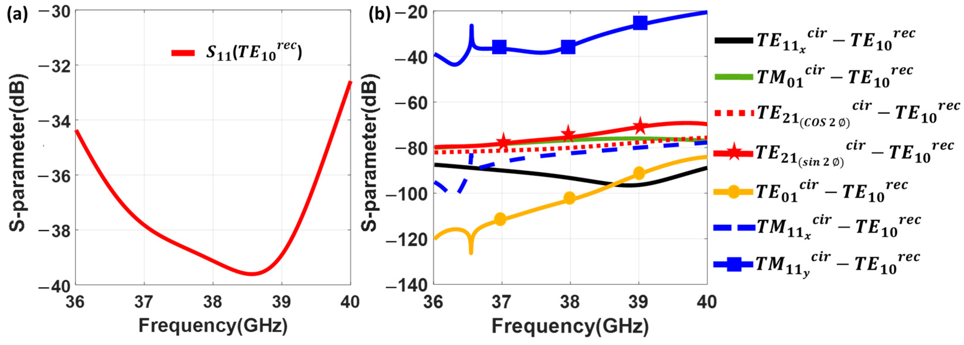
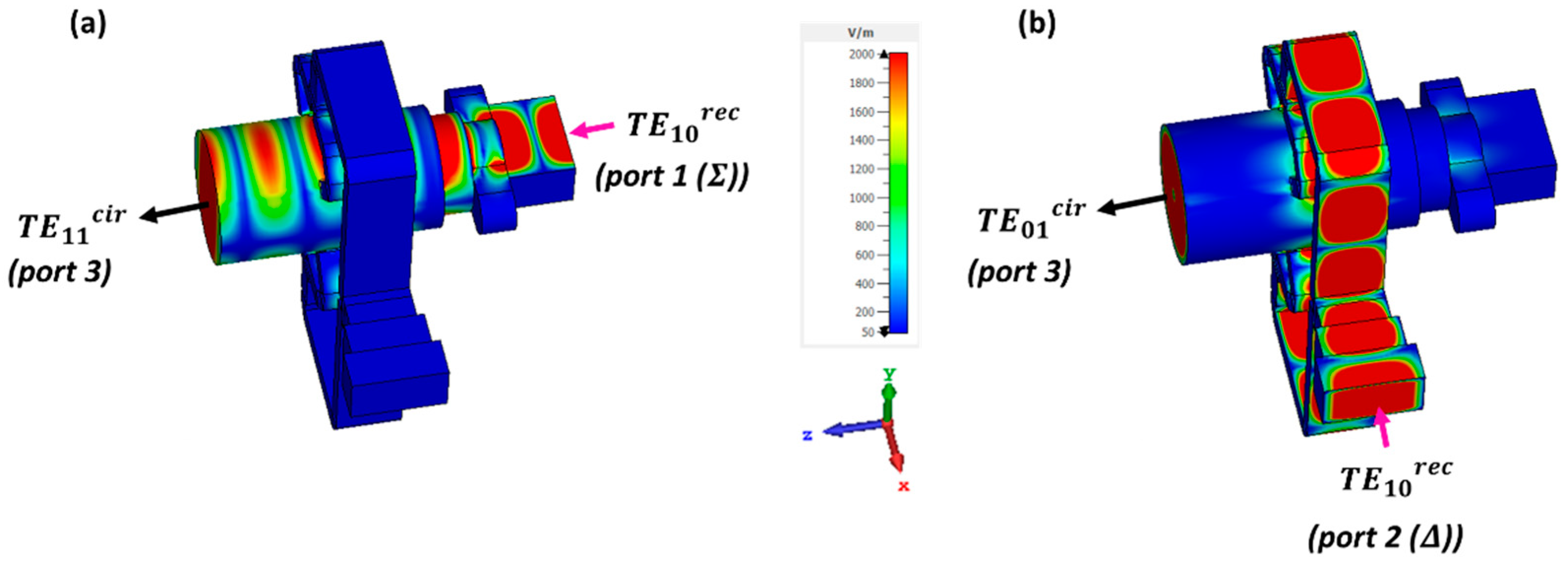
2.1. Mode Converter from Mode in the Rectangular Waveguide to the Mode in the Circular Waveguide
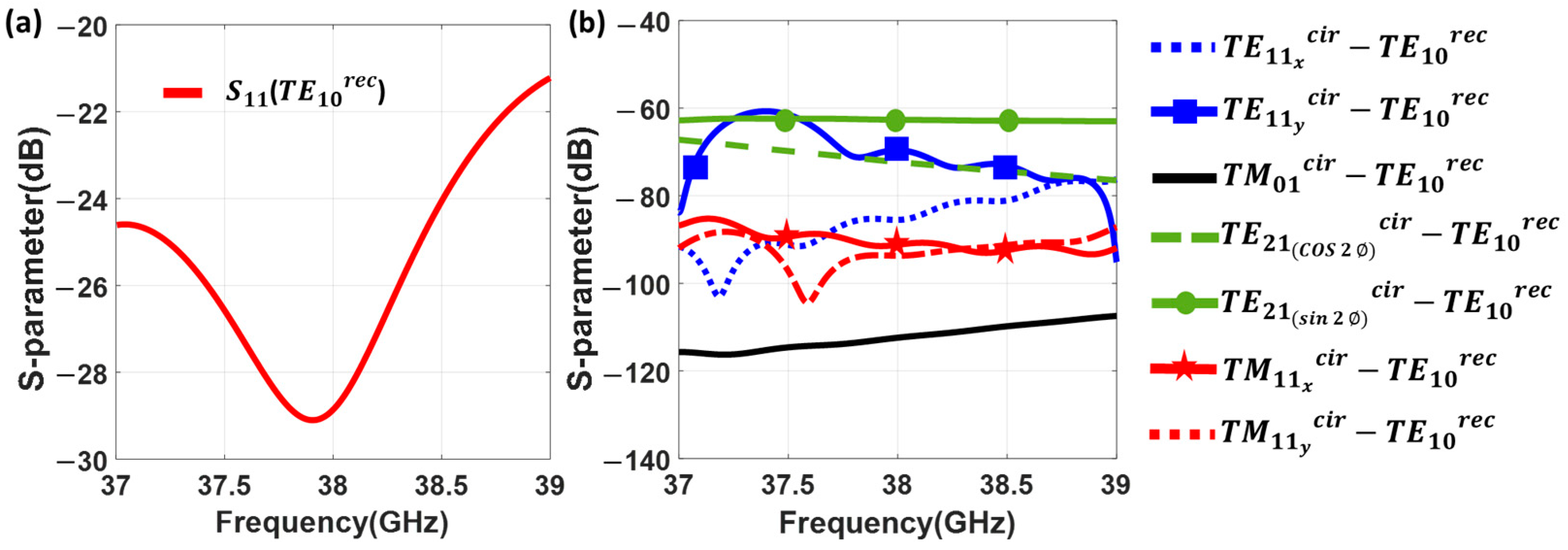
2.2. Mode Converter from the Mode in the Rectangular Waveguide to the Mode in the Circular Waveguide
3. Integration of the Dual-Mode Converter and the Conical Horn Antenna
3.1. Integration of the and Mode Converters for Obtaining the Dual-Mode Converter (DMC)
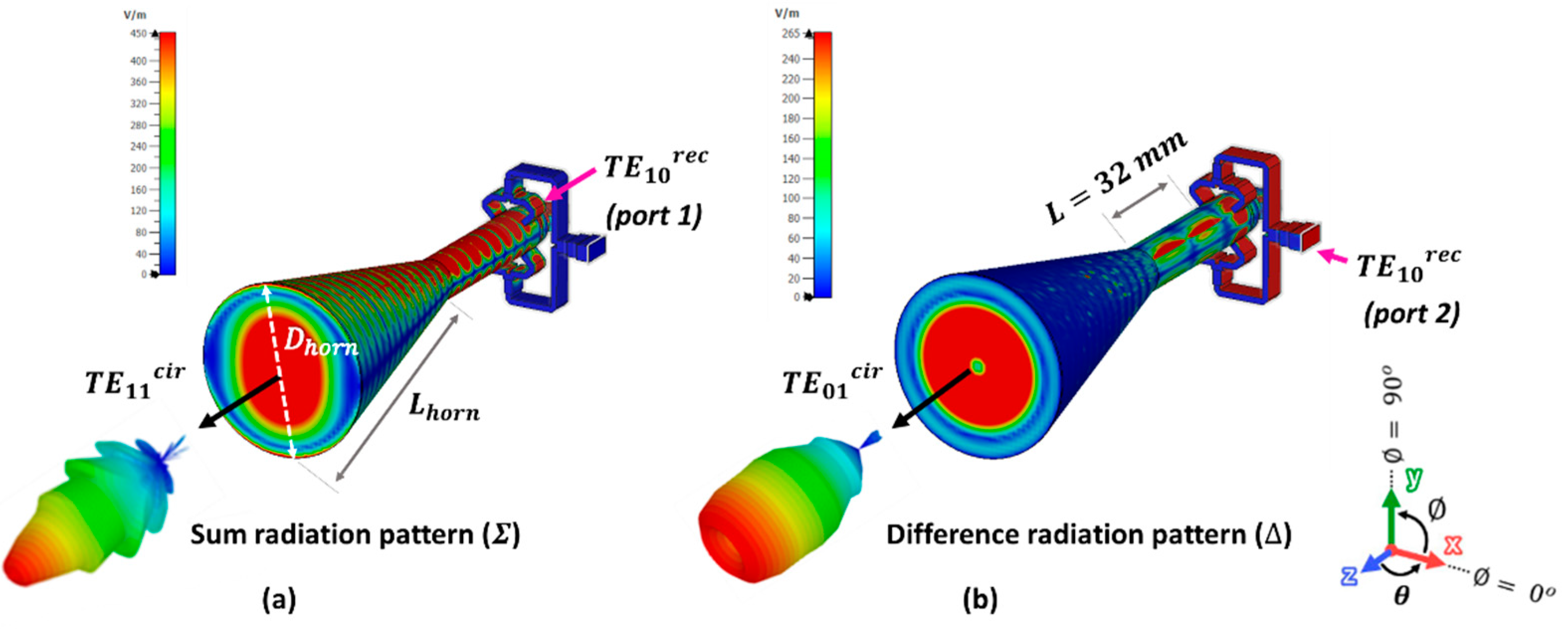
3.2. Integration of the Dual-Mode Converter (DMC) with the Conical Horn Antenna (CHA) for Obtaining the Dual-Mode Conical Horn Antenna (DM-CHA)
3.3. Full-Wave Simulations of the DMC and the DM-CHA
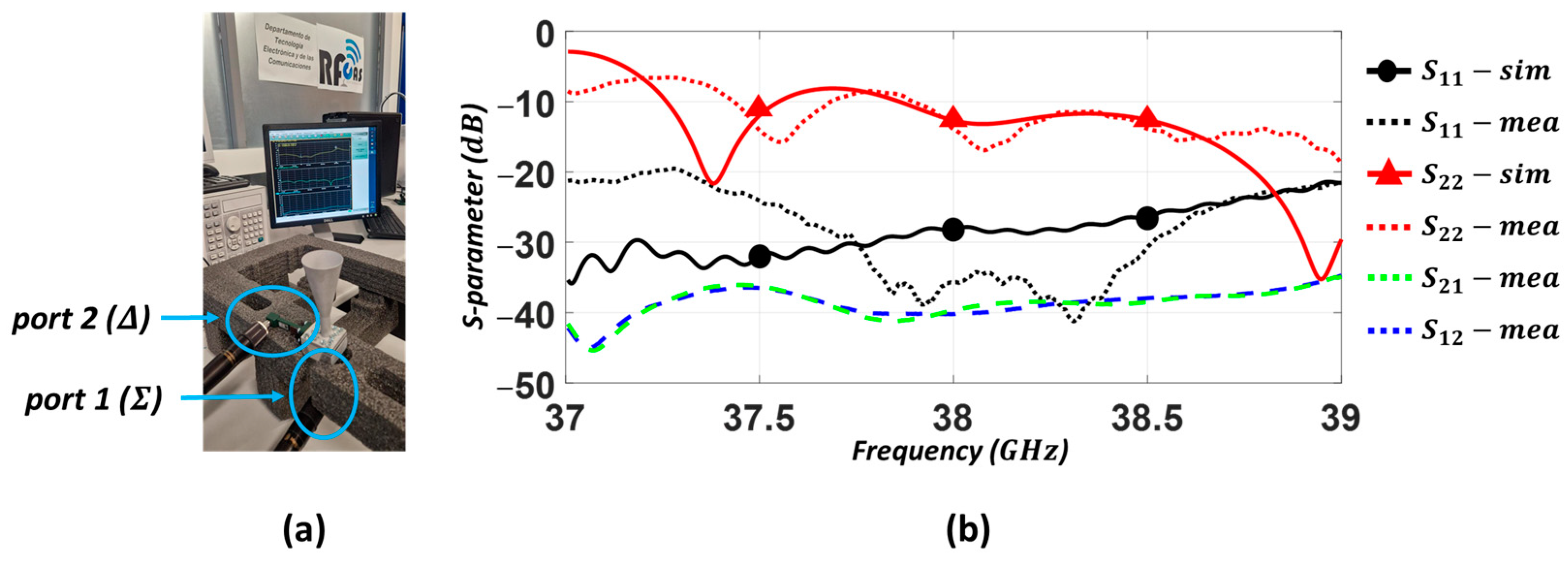
4. Experimental Results
5. Conclusions
Author Contributions
Funding
Institutional Review Board Statement
Informed Consent Statement
Data Availability Statement
Conflicts of Interest
References
- Skolnik, M. Introduction to Radar Systems, 2nd ed.; Electrical Engineering Series; McGraw-Hill: New York, NY, USA, 1980. [Google Scholar]
- Sherman, S.; Barton, D. Monopulse Principles and Techniques (Artech House Radar Library); Artech House: Norwood, MA, USA, 2011. [Google Scholar]
- Chu, C.; Zhu, J.; Liao, S.; Xue, Q.; Zhu, A. Dual-Polarized Substrate Integrated-Waveguide Cavity-Backed Monopulse Antenna Array for 5G Millimeter-Wave Applications. In Proceedings of the IEEE MTT-S International Microwave Conference on Hardware and Systems for 5G and Beyond (IMC-5G), Altanta, GA, USA, 15–16 August 2019. [Google Scholar]
- Hu, C.N.; Xu, W.J.; Gao, R.Z.; Cai, Z.T.; Chen, X.Z.; Wu, C.C.; Lo, P. Monopulse Tracking Method for Angle Estimation in 5G Millimeter-Wave Channel Sounder. In Proceedings of the International Workshop on Electromagnetics: Applications and Student Innovation Competition (iWEM), Penghu, Taiwan, 26–28 August 2020. [Google Scholar]
- Barton, D.K. Development of the AN/FPS-16 instrumentation radar. IEEE Aerosp. Electron. Syst. Mag. 2011, 26, B1–B16. [Google Scholar] [CrossRef]
- Kuecken, J. Feed optimization in multi-feed antennas. In Proceedings of the WESCON/57 Conference Record, San Francisco, CA, USA, 20–23 August 1957. [Google Scholar]
- Hannan, P. Optimum feeds for all three modes of a monopulse antenna II: Practice. IRE Trans. Antennas Propag. 1961, 9, 454–461. [Google Scholar] [CrossRef]
- Shelton, J. Improved feed design for amplitude monopulse radar antennas. In Proceedings of the 1958 IRE International Convention Record, New York, NY, USA, 21–25 March 1966; IEEE: Piscataway, NJ, USA, 1959. [Google Scholar]
- Olver, A.; Clarricoats, P.; Kishk, A.; Shafai, L. Microwave Horns and Feeds; Electromagnetic Waves Series; IEE: London, UK, 1994. [Google Scholar]
- Clarricoats, P.J.B.; Elliot, R.D. Multimode corrugated waveguide feed for monopulse radar. IEE Proc. H Microw. Opt. Antennas 1981, 128, 102–110. [Google Scholar] [CrossRef]
- Ferreras, M.; Barba, M.; Grajal, J. Calibration of a 94-GHz Monopulse Feed based on Hybrid Comparison of its Experimental Patterns. In Proceedings of the 16th European Conference on Antennas and Propagation (EuCAP), Madrid, Spain, 27 March–1 April 2022. [Google Scholar]
- Yu, Z.W.; Wang, G.M.; Zhang, C.X. A Broadband Planar Monopulse Antenna Array of C-Band. IEEE Antennas Wirel. Propag. Lett. 2009, 8, 1325–1328. [Google Scholar]
- Chepala, A.; Rao Ghali, V.R.; Daggula, R. X-band Planar Monopulse Microstrip Antenna array with improved null-depth. In Proceedings of the 15th European Conference on Antennas and Propagation (EuCAP), Dusseldorf, Germany, 22–26 March 2021. [Google Scholar]
- Wang, H.; Fang, D.G.; Chen, X.G. A compact single layer monopulse microstrip antenna array. IEEE Trans. Antennas Propag. 2006, 54, 503–509. [Google Scholar] [CrossRef]
- Phyoe, T.P.; Nishiyama, E.; Toyoda, I. A 5.8-GHz Dual-Axis Monopulse Microstrip Array Antenna Using Dual-Feed Network. In Proceedings of the Asia-Pacific Microwave Conference (APMC), Kyoto, Japan, 6–9 November 2018. [Google Scholar]
- Kumar, H.; Kumar, G. Broadband monopulse microstrip antenna array for x-band monopulse tracking. IET Microw. Antennas Propag. 2018, 12, 2109–2114. [Google Scholar] [CrossRef]
- Jahagirdar, D.R.; Borkar, V.G. A high efficiency Ku-band printed monopulse array. In Proceedings of the IEEE Antennas and Propagation Society International Symposium, Toronto, ON, Canada, 11–17 July 2010. [Google Scholar]
- Colak, O.; Sahinkaya, D.S.A. SLL suppressed monopulse microstrip antenna design. In Proceedings of the IEEE Antennas and Propagation Society International Symposium (APSURSI), Memphis, TN, USA, 6–12 July 2014. [Google Scholar]
- Faenzi, M.; González-Ovejero, D.; Petraglia, G.; D’Alterio, G.; Pascariello, F.; Vitiello, R.; Maci, S. A Metasurface Radar Monopulse Antenna. IEEE Trans. Antennas Propag. 2022, 70, 2571–2579. [Google Scholar] [CrossRef]
- Liu, B.; Hong, W.; Kuai, Z.; Yin, X.; Luo, G.; Chen, J.; Tang, H.; Wu, K. Substrate Integrated Waveguide (SIW) Monopulse Slot Antenna Array. IEEE Trans. Antennas Propag. 2009, 57, 275–279. [Google Scholar] [CrossRef]
- Zhu, J.; Liao, S.; Li, S.; Xue, Q. 60 GHz Substrate-Integrated Waveguide-Based Monopulse Slot Antenna Arrays. IEEE Trans. Antennas Propag. 2018, 66, 4860–4865. [Google Scholar] [CrossRef]
- Cheng, Y.J.; Hong, W.; Wu, K. 94 GHz Substrate Integrated Monopulse Antenna Array. IEEE Trans. Antennas Propag. 2012, 60, 121–129. [Google Scholar] [CrossRef]
- Cao, F.; Yang, D.; Pan, J.; Geng, D.; Xiao, H. A Compact Single-Layer Substrate-Integrated Waveguide (SIW) Monopulse Slot Antenna Array. IEEE Antennas Wirel. Propag. Lett. 2017, 16, 2755–2758. [Google Scholar] [CrossRef]
- Yang, T.; Zhao, Z.; Yang, D.; Liu, X.; Liu, Q.-H. A Single-Layer SIW Slots Array Monopulse Antenna Excited by a Dual-Mode Resonator. IEEE Access 2019, 7, 131282–131288. [Google Scholar] [CrossRef]
- Zhang, Y.-X.; Jiao, Y.-C.; Zhang, L.; Wen, J.-X. Wideband 2-D Monopulse Antenna Array with Higher-Order Mode Substrate Integrated Waveguide Feeding and 3-D Printed Packaging. IEEE Trans. Antennas Propag. 2020, 68, 3259–3264. [Google Scholar] [CrossRef]
- Chu, H.; Chen, J.-X.; Luo, S.; Guo, Y.-X. A Millimeter-Wave Filtering Monopulse Antenna Array Based on Substrate Integrated Waveguide Technology. IEEE Trans. Antennas Propag. 2016, 64, 316–321. [Google Scholar] [CrossRef]
- Vosoogh, A.; Haddadi, A.; Zaman, A.U.; Yang, J.; Zirath, H.; Kishk, A. W -Band Low-Profile Monopulse Slot Array Antenna Based on Gap Waveguide Corporate-Feed Network. IEEE Trans. Antennas Propag. 2018, 66, 6997–7009. [Google Scholar] [CrossRef]
- Ferrando-Rocher, M.; Herranz-Herruzo, J.I.; Valero-Nogueira, A.; Bernardo-Clemente, B. All-Metal Monopulse Antenna Array in the Ka-Band with a Comparator Network Combining Ridge and Groove Gap Waveguides. IEEE Antennas Wirel. Propag. Lett. 2023, 22, 1381–1385. [Google Scholar] [CrossRef]
- Bayer, H.; Krauss, A.; Stephan, R.; Hein, M.A. Compact Ka-band Cassegrain antenna with multimode monopulse tracking feed for satcom-on-the-move applications. In Proceedings of the 10th European Conference on Antennas and Propagation (EuCAP), Davos, Switzerland, 10–15 April 2016. [Google Scholar]
- Monebi, A.M.; Lee, C.-S.; Ahn, B.-C.; Choi, S.-G. Design of a Ku-Band Monopulse Antenna with a Truncated Reflector and an Open-Ended Waveguide Feed. Sensors 2023, 23, 118. [Google Scholar] [CrossRef]
- Monebi, A.M.; Otgonbat, D.; Ahn, B.-C.; Lee, C.-S.; Ahn, J.-H. Conceptual Design of a Semi-Dual Polarized Monopulse Antenna by Computer Simulation. Appl. Sci. 2023, 13, 2960. [Google Scholar] [CrossRef]
- Shen, R.; Ye, X.; Miao, J. Design of a multimode feed horn applied in a tracking antenna. IEEE Trans. Antennas Propag. 2017, 65, 2779–2788. [Google Scholar] [CrossRef]
- Liu, R.J.; Dou, W.B. Design and analysis of 3 mm multimode monopulse feed. In Proceedings of the 2007 International Conference on Microwave and Millimeter Wave Technology, Guilin, China, 18–21 April 2007. [Google Scholar]
- Hongjian, W. Multimode horn for a monopulse subsystem. In Proceedings of the 2019 IEEE International Symposium on Antennas and Propagation and USNC-URSI Radio Science Meeting, Atlanta, GA, USA, 7–12 July 2019. [Google Scholar]
- Polo-López, L.; Córcoles, J.; Ruiz-Cruz, J.A.; Montejo-Garai, J.R.; Rebollar, J.M. Triple-Radiation Pattern Monopulse Horn Feed with Compact Single-Layer Comparator Network. IEEE Trans. Antennas Propag. 2021, 69, 2546–2559. [Google Scholar] [CrossRef]
- El-Tager, A.M.; Ahmad, H.N.; Darwish, M.M. Multimode antenna feed system for an X-band monopulse radar. In Proceedings of the 2009 IEEE Radar Conference, Pasadena, CA, USA, 4–8 May 2009. [Google Scholar]
- Ferreras, M.; Barba, M.; Grajal, J. A 94 GHz Monopulse Duplexing Horn Antenna for a 3-D Tracking Radar. IEEE Trans. Antennas Propag. 2022, 70, 8973–8982. [Google Scholar] [CrossRef]
- Pandey, A.K. Design of multimode tracking system for Earth station antenna. In Proceedings of the 2016 Asia-Pacific Microwave Conference (APMC), New Delhi, India, 5–9 December 2016. [Google Scholar]
- Guan, B.; Kuang, Y.; Chen, Z.P. Canceling the Cross-Polarization of the Difference Modes in a Circular Aperture Multimode Monopulse Feed, IEEE Trans. Antennas Propag. 2018, 66, 6734–6741. [Google Scholar] [CrossRef]
- Meyer, E.; Bressner, T.A.H.; Bart Smolders, A.B.; Johannsen, U. Miniaturized Conical Waveguide Filtenna for 5G Millimeter Wave Base Stations. In Proceedings of the 15th European Conference on Antennas and Propagation (EuCAP), Dusseldorf, Germany, 22–26 March 2021. [Google Scholar]
- Simionato, E.; Zang, S.R.; Aldaya, I.; de Oliveira, J.A.; Rosa, G.S.; Penchel, R.A. Novel coaxial transition for shaped coaxial horn antennas operating at millimeter wave frequencies. In Proceedings of the IEEE International Symposium on Antennas and Propagation and USNC-URSI Radio Science Meeting (AP-S/URSI), Denver, CO, USA, 10–15 July 2022. [Google Scholar]
- Zhang, P.; Qi, J.; Qiu, J. Efficient design of axially corrugated coaxial-type multi-band horns for reflector antennas. Int. J. Microw. Wirel. Technol. 2017, 9, 1975–1981. [Google Scholar] [CrossRef]
- Schneider, M.; Hartwanger, C.; Kilian, M. Antenna Concepts and Technologies for Future 5G Satellites. In Proceedings of the 2019 IEEE 2nd 5G World Forum (5GWF), Dresden, Germany, 30 September–2 October 2019. [Google Scholar]
- Chen, M.H. A 19-way isolated power divider via the TE 01 circular waveguide mode transition. In Proceedings of the 1986 IEEE MTT-S International Microwave Symposium Digest, Baltimore, MD, USA, 2–4 June 1986. [Google Scholar]
- Chu, Q.-X.; Mo, D.-Y.; Wu, Q.-S. An isolated radial power divider via circular waveguide TE 01 -mode transducer. IEEE Trans. Microw. Theory Techn. 2015, 63, 3988–3996. [Google Scholar] [CrossRef]
- Montejo-Garai, J.R.; Ruiz-Cruz, J.A.; Rebollar, J.M. 5-Way Radial Power Combiner at W-band by Stacked Waveguide Micromachining. Nucl. Instrum. Methods Phys. Res. Sect. A Accel. Spectrometers Detect. Assoc. Equip. 2018, 905, 91–95. [Google Scholar] [CrossRef]
- Montejo-Garai, J.R.; Saracho-Pantoja, I.O.; Ruiz-Cruz, J.A.; Rebollar, J.M. High-performance 16-way Ku-band radial power combiner based on the TE01- circular waveguide mode. Rev. Sci. Instrum. 2018, 89, 034703. [Google Scholar] [CrossRef] [PubMed]
- Buckley, M.J.; Vernon, R.J. Compact quasi-periodic and aperiodic TE/sub 0n/mode converters in over moded circular waveguides for use with gyrotrons. IEEE Trans. Microw. Theory Tech. 1990, 38, 712–721. [Google Scholar] [CrossRef]
- Pierre, M.G.R. Mode Transforming Wave Guide Transition. U.S. Patent No. 2,859,412, 4 November 1958. [Google Scholar]
- Gonzalez-Calvo, M.; Montejo-Garai, J.R.; Ruiz-Cruz, J.A.; Rebollar, J.M. Additive Manufacturing of a High-Performance Q-Band Circular TE01 Mode Flared-Type Transducer. IEEE Microw. Wirel. Compon. Lett. 2019, 29, 577–579. [Google Scholar] [CrossRef]
- Yu, C.F.; Chang, T.H. High Performance Circular TE01, Mode Converter. In Proceedings of the IEEE International Conference on Plasma Science, Monterey, CA, USA, 20–23 June 2005. [Google Scholar]
- Piroutiniya, A.; Rasekhmanesh, M.H.; Masa-Campos, J.L.; Calero-Rodríguez, J.L.; Ruiz-Cruz, J.A. Dual Mode Monopulse Conical Horn Antenna for 5G Millimeter-Wave Band Applications. In Proceedings of the 2023 17th European Conference on Antennas and Propagation (EuCAP), Florence, Italy, 26–31 March 2023. [Google Scholar]
- Uher, J.; Bornemann, J.; Rosenberg, U. Waveguide Components for Antenna Feed Systems; Artech House: Boston, MA, USA, 1993. [Google Scholar]
- Mediavilla, A.; Cano, J.L.; Cepero, K. On the octave bandwidth properties of octagonal-shaped waveguide mode transformers. IEEE Trans. Microw. Theory Tech. 2011, 59, 2447–2451. [Google Scholar] [CrossRef]
- Holzman, E.L. A simple circular-to-rectangular waveguide transition. IEEE Microw. Wirel. Compon. Lett. 2005, 15, 25–26. [Google Scholar] [CrossRef]
- Ruiz-Cruz, J.A.; Montejo-Garai, J.R.; Rebollar, J.M. Multi-Section Bow-Tie Steps for Full-Band Waveguide Polarization Rotation. IEEE Microw. Wirel. Compon. Lett. 2010, 20, 375–377. [Google Scholar] [CrossRef]
- Marcuvitz, N. Waveguide Handbook; McGraw-Hill: New York, NY, USA, 1951. [Google Scholar]
- Collin, R.E. Foundations for Microwave Engineering; McGraw-Hill International Editions: New York, NY, USA, 1966. [Google Scholar]
- CST Studio Suite. 2022. Available online: https://www.3ds.com/es/productos-y-servicios/simulia/productos/cst-studio-suite/ (accessed on 8 August 2023).
- Montejo-Garai, J.R.; Saracho-Pantoja, I.O.; Ruiz-Cruz, J.A.; Rebollar, J.M. Broadband and high-purity Ku-band circular TE01-mode converter. In Proceedings of the 2016 Asia-Pacific Microwave Conference (APMC), New Delhi, India, 5–9 December 2016. [Google Scholar]
- Anechoic Chamber of Escuela Politécnica Superior, Universidad Autónoma de Madrid, Madrid, Spain. Available online: http://rfcas.eps.uam.es/web/?q=en/anecoica (accessed on 8 August 2023).
- Balanis, C.A. Antenna Theory: Analysis and Design; Wiley-Interscience: New York, NY, USA, 2005. [Google Scholar]


Disclaimer/Publisher’s Note: The statements, opinions and data contained in all publications are solely those of the individual author(s) and contributor(s) and not of MDPI and/or the editor(s). MDPI and/or the editor(s) disclaim responsibility for any injury to people or property resulting from any ideas, methods, instructions or products referred to in the content. |
© 2023 by the authors. Licensee MDPI, Basel, Switzerland. This article is an open access article distributed under the terms and conditions of the Creative Commons Attribution (CC BY) license (https://creativecommons.org/licenses/by/4.0/).
Share and Cite
Piroutiniya, A.; Rasekhmanesh, M.H.; Masa-Campos, J.L.; Calero-Rodríguez, J.L.; Ruiz-Cruz, J.A. Dual-Mode Conical Horn Antenna with 2-D Azimuthal Monopulse Pattern for Millimeter-Wave Applications. Sensors 2023, 23, 8157. https://doi.org/10.3390/s23198157
Piroutiniya A, Rasekhmanesh MH, Masa-Campos JL, Calero-Rodríguez JL, Ruiz-Cruz JA. Dual-Mode Conical Horn Antenna with 2-D Azimuthal Monopulse Pattern for Millimeter-Wave Applications. Sensors. 2023; 23(19):8157. https://doi.org/10.3390/s23198157
Chicago/Turabian StylePiroutiniya, Asrin, Mohamad Hosein Rasekhmanesh, José Luis Masa-Campos, José Luis Calero-Rodríguez, and Jorge A. Ruiz-Cruz. 2023. "Dual-Mode Conical Horn Antenna with 2-D Azimuthal Monopulse Pattern for Millimeter-Wave Applications" Sensors 23, no. 19: 8157. https://doi.org/10.3390/s23198157