Table of Contents
Advertisement
Advertisement
Table of Contents

Summary of Contents for Proteco LEADER 3
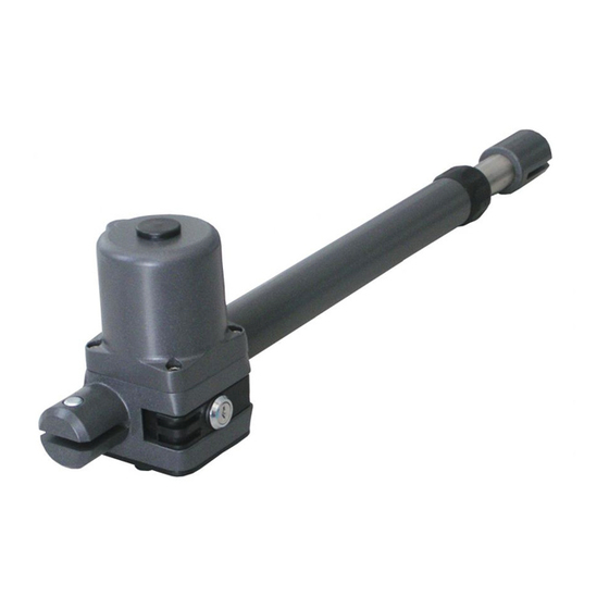
- Page 1 INSTALLATION MANUAL LEADER Gearmotor for swing gates...
-
Page 3: Table Of Contents
Index SAFETY INSTRUCTIONS ............................pag. 01 COMPLIANCE DECLARATION ........................... pag. 01 DESCRIPTION AND INTENDED USE ........................pag. 01 Technical data ............................pag. 02 Kit content ............................... pag. 02 Dimensions ............................. pag. 02 INSTALLATION ..............................pag. 03 Preliminary checks ..........................pag. 03 Wiring ................................ -
Page 4: Safety Instructions
LEADER electromechanical gear motor for swing gates Models: LEADER 3 TI, LEADER 4 TI, LEADER 5 TI, LEADER 24 3 TI, LEADER 24 4 TI, LEADER 24 5 TI LEADER 3 TA, LEADER 24 4 TA Is built to be integrated into a machine or to be assembled with other machinery to crate a machine under provisions of 2006/42/EC Machinery Directive, with reference in particular to the following requirements: 1.1.2 1.1.3 1.1.5 1.2.1 1.2.2 1.2.3 1.2.6 1.3.2 1.3.4 1.3.9 1.4.1... -
Page 5: Technical Data
(24V) (24V) Leader 3 TI = 665 - Leader 4 TI = 765 - Leader 5 TI = 865 mm Leader 4 TA = 885 Leader 3 TI = 965 - Leader 4 TI = 1165 - Leader 5 TI = 1365 mm... -
Page 6: Installation
INSTALLATION Preliminary checks Before installing make sure: • The gate conditions are suitable to automate. • Weight, dimensions and gate construction are proper for the operator you intend to buy. • You have suitable mechanical ground stops. • The automated parts are in good mechanical conditions. •... -
Page 7: Establishing Rh And Lh Operator
Ensure you are mounting the correct handed motor to the leaf (see picture 3, inner view). Make sure there are mechanical ground stops in opening 345 mm LEADER 3 TI and closing (see picture B). 445 mm LEADER 4 TI... - Page 8 Fig. 8 LEADER 3 TI = max 150 mm LEADER 4 TI = max 250 mm LEADER 4 TA = max 200 mm LEADER 5 TI = max 275 mm OUTER VIEW OUTER VIEW INNER VIEW INNER VIEW 90° 90°...
-
Page 9: Outward Opening
3.4.3 OUTWARD OPENING Your gate can be automated for opening outwards too. In this case the value of A dimension shall be calculated towards the gate center. See picture 9 and 10 and fit the bracket accordingly. Fig. 9 Fig. 10 90°... -
Page 10: Releasing The Gearmotor
3.6.2 LEADER TA Fig. 15 To determine the position of bracket S4: Put the gate in closing position Release the gearmotor Slide the front drive pin to the closing limit-switch point (keep a distance of 45 mm between the pin and the pipe end terminal (see picture 15). - Page 11 LEADER TI 22 A 230V 22 B...
- Page 12 LEADER TA 22 A 22 B Proteco S.r.l. Via Neive, 77 - 12050 CASTAGNITO (CN) ITALY Tel. +39 0173 210111 - Fax +39 0173 210199 - info@proteco.net - www.proteco.net...