What is a zener diode
A Zener diode is a type of diode in which a P-type semiconductor and an N-type semiconductor fuse together to form a PN junction, around which a depletion layer with reverse-phase ions is formed. It is characterized by the use of PN junction reverse breakdown, the current can be changed in a large range and the voltage is basically unchanged, so as to play a role in voltage regulation. Zener diodes are graded according to breakdown voltage and are widely used in voltage regulator and limiter circuits. The circuit diagram symbol and common voltage regulator diode appearance are shown in the figures below.
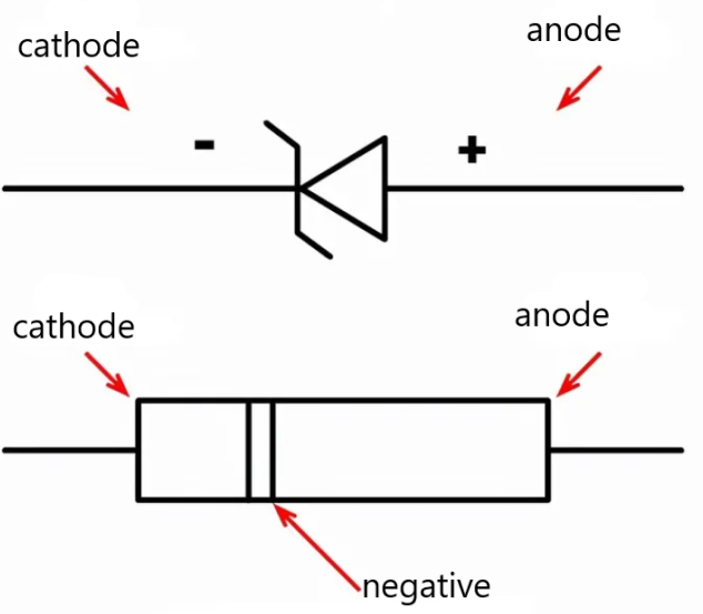 Figure 1:Zener diode circuit symbol diagram
Figure 2: Zener diode circuit diagram
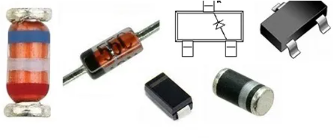
Figure 3: Common Zener diode configuration
How does a zener diode do
Zener diodes act like ordinary diodes when forward-biased. Then, once the reverse voltage is equal to its rated voltage, the current is allowed to flow in the opposite direction.
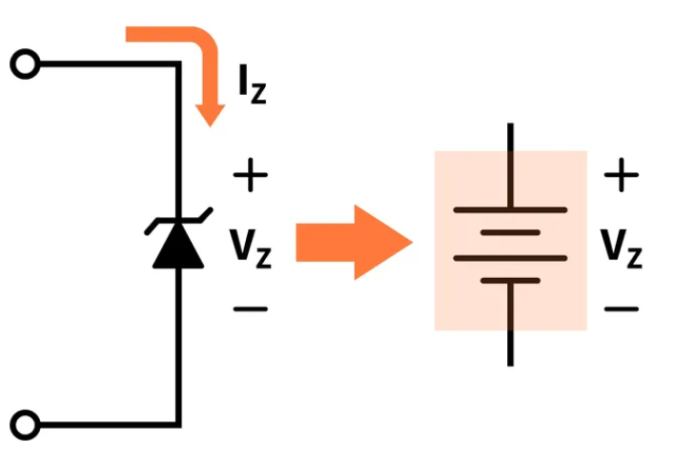
Figure 4: Zener diode DC voltage diagram
The breakdown operating Zener diode acts as a voltage regulator because it maintains an almost constant voltage across its terminals within a specified range of reverse current values, which is equal to the Zener voltage. The constant voltage drop at both ends of the Zener diode resulting from the reverse breakdown is represented by the DC voltage symbol.
Difference Between Zener Diodes and Simple Diodes
1 doping degree, simple diode is moderately doped, Zener diode is heavily doped, in order to achieve a higher breakdown voltage. The varying degree of doping contributes to their specifications for operating at different voltage levels.
2 electrical conductivity, due to the high doping of Zener diodes, compared with the PN junction of simple diodes, the depletion layer of Zener diode PN junction is very thin, which provides special characteristics for Zener diodes, and can conduct electricity under both forward and reverse bias conditions.
VI Characteristics of Zener Diodes
The figure below shows the VI property of a Zener diode, which allows only a small amount of leakage current when a reverse bias voltage is applied to the Zener diode until the voltage falls below the Zener voltage.
Figure 5: VI characteristics of Zener diode
The VI characteristics of Zener diodes can be divided into the following two parts:
1 Forward characteristics
2 Reverse characteristics
Forward characteristics of a Zener diode: In the figure above, the first quadrant represents the forward characteristics of a Zener diode. You can see from the figure that it has almost the same forward characteristics as any other PN junction diode.
Reverse characteristics of Zener diodes: When the reverse voltage is applied to the Zener voltage, there is initially a small reverse saturation current Lo flowing through the diode. The current is caused by a small number of carriers produced by heat. With the increase of reverse voltage, the reverse current increases sharply under a certain reverse voltage. This indicates that something has gone wrong. We call this the breakdown voltage or Zener voltage, which is represented by Vz.
Functions of zener diode
- Voltage Regulation: Perhaps the most significant use of Zener diodes is voltage regulation. They maintain a nearly constant output voltage even when the input voltage or load current changes, making them invaluable in power supply circuits.
- Voltage Shifter: Zener diodes can also function as voltage shifters. When used in series with a power supply, they can create a lower output voltage.
- Waveform Clipping: In signal processing circuits, Zener diodes are used to clip the waveform to prevent signal peaks from exceeding certain levels.
- Protection of Circuits: Zener diodes are often used in surge protectors to limit transient voltage spikes.
- Voltage Reference: In many circuits, Zener diodes provide a reference voltage. This can be used for a variety of purposes, such as generating a stable voltage for analog-to-digital or digital-to-analog converters.
Remember, the specific function of a Zener diode in a circuit will depend on how it's connected - either in a 'reverse bias' mode (most common for voltage regulation) or 'forward bias' mode.
Uses of zener diode
- Voltage Regulation: The primary use of Zener diodes is to regulate voltage. They are used in circuits to maintain a steady output voltage despite changes in input voltage or load conditions.
- Voltage Reference: Zener diodes can provide a reference voltage in various circuits. This is useful in applications such as voltage dividers.
- Waveform Clipping: In signal processing circuits, Zener diodes are used for waveform clipping. This helps in limiting signal voltage to a certain level, preventing it from exceeding the desired amplitude.
- Voltage Shifter: When used in series with a power supply, Zener diodes can create a lower output voltage, effectively shifting the voltage level.
- Surge Protection: Zener diodes can protect circuits from voltage spikes. When a voltage spike occurs, the Zener diode breaks down and allows current to flow in the reverse direction, clamping the voltage to a safe level.
- Switching Operations: While not as common, Zener diodes can also be used in certain switching operations in some types of circuits.
- As a Noise Generator: In some specialized applications, the noise generated by the Zener breakdown effect can be used as a random noise source.
How to test zener diode
- Disconnection: Disconnect the Zener diode from the circuit it's a part of. This is important as other components in the circuit can interfere with the testing process.
- Visual Inspection: Before using any testing tools, perform a visual inspection to look for any obvious signs of damage.
- Use a Multimeter/Diode Tester: Most multimeters have a diode check function. First, you need to identify the cathode (negative) and anode (positive) leads of the Zener diode. Then set the multimeter to the diode check function and connect the positive (red) lead of the multimeter to the anode and the negative (black) lead to the cathode. The multimeter should display a reading.
- Reverse Bias Test: Swap the leads (negative to anode and positive to cathode). The multimeter should show an 'OL' reading for a good Zener diode, indicating that it's blocking the current flow as it should in reverse bias.
- Zener Voltage Test: To test the Zener voltage, you'll need a DC power supply, a resistor to limit the current, and a voltmeter. Connect the power supply, resistor, Zener diode, and voltmeter in series (in this order). The Zener diode should be reverse biased. Adjust the power supply voltage to be slightly higher than the Zener voltage of the diode. The voltmeter will read the Zener voltage.
Advantages and Disadvantages of Zener Diodes
Advantages:
- Voltage Regulation: Zener diodes are excellent voltage regulators. They can maintain a nearly constant output voltage, even when the input voltage or load current changes.
- Precision: Zener diodes can provide a precise reference voltage, which makes them useful in several applications where precision is required.
- Protection: Zener diodes can protect circuits from voltage spikes by clamping the voltage to the Zener voltage.
- Compact Size: Zener diodes are small and lightweight, which makes them suitable for compact devices and circuits.
Disadvantages:
- Power Limitations: Zener diodes are not suitable for high power applications. They can only handle a small amount of current and can easily burn out if too much current passes through them.
- Temperature Sensitivity: The Zener voltage can change with temperature, which can affect the performance of the diode.
- Noise: Zener diodes can generate noise in a circuit, especially at high currents.
- Limited Voltage Range: The Zener voltage is typically available in a limited range of values, which can limit their use in some applications.
Zener diode main specifications
1 Voltage regulator VZ
The Zener voltage, also known as the breakdown voltage, is the reverse bias voltage that causes a diode to conduct current. Breakdown voltages typically range from 2.4V to hundreds of volts, depending on the particular Zener diode.
2 Maximum current (Iz-max)
Iz-max is the maximum current that can flow through a Zener diode at reverse breakdown voltage. It ranges from 200μA to 200A. Iz-max can be calculated using the following formula:
Iz=Pz/Vz
Where Pz is the maximum power the diode can handle and Vz is the reverse breakdown voltage.
3 Minimum current (Iz-min)
Iz-min is the minimum current required to cause a Zener diode to break down. It ranges from 5mA to 10mA.
4 Test Current (IZ)
For each Zener diode, the Zener voltage (VZ) is measured at the specified Zener test current (IZ). For example, the 1N4732A has a Zener voltage range of 4.465 to 4.935V, with a typical value of 4.7V and a test current of 53mA.
5 Inflection Point Current (IZK)
Maintain the minimum current required for diode breakdown voltage regulation. Typical values for a 1 watt zener diode are about 0.25 to 1mA. If this current is not reached, the diode will not break down sufficiently to maintain its rated voltage.
6 Leakage current
Reverse leakage current is specified for reverse voltages less than the inflection point voltage. This means that the Zener diode has no reverse breakdown for these measurements. For example, the reverse voltage in a 1N4728A is 1V.
7 Rated Power (Pz)
The rated power is the maximum power that a Zener diode can safely dissipate. Common power ratings for Zener diodes include 400 mW, 500 MW, 1mW, 3mW, and 5mW. Zener diodes with high power ratings are often expensive, and they require additional equipment to remove excess heat. The maximum power consumption (Pzm) of a Zener diode can be calculated by a given formula.
Pzm=Iz*Vz
Iz is the maximum current that can flow through the Zener diode, and Vz is the Zener breakdown voltage.
8 Zener diode tolerance
The tolerance of a nanodiode is defined as the voltage range close to the breakdown voltage in which the Zener diode conducts current in a reverse bias. In the process of manufacturing a voltage regulator, the doping concentration of the same voltage regulator may be slightly different, which means that their breakdown voltage is also slightly different, so the same voltage regulator will conduct the reverse current at different reverse breakdown voltage values, and this range of Zener breakdown voltage is called their tolerance. Typically, Zener diodes have a voltage tolerance of ±5%.
9 junction temperature
In order to ensure the reliability of the diode, the junction temperature is the key. Even though the shell may be cold enough, the active area can still be very hot. Therefore, some manufacturers specify the end of their own scope of work. For normal designs, an appropriate margin is usually left between the maximum expected temperature and the junction within the device. The temperature inside the device is higher than the temperature outside the device. Although the ambient temperature outside the device is acceptable, care must be taken to ensure that individual items do not become too hot.
10 Package
Zener diodes come in a variety of different packages. The primary choice is between surface mount and conventional through-hole devices. However, the package selected usually determines the heat dissipation level of the package, and the package is selected according to the requirements of the internal heat dissipation level of the device, which can refer to the relevant Zener diode datasheet.
Zener diode breakdown
The breakdown in a Zener diode refers to the condition where the diode starts conducting current in the reverse direction. This happens when the voltage across the diode exceeds a certain level known as the breakdown voltage or Zener voltage.
In normal diodes, breakdown is usually an undesirable condition that can cause the diode to fail. However, in Zener diodes, this breakdown is intentionally engineered and utilized in their operation. The Zener breakdown effect allows the diode to maintain a nearly constant voltage across its terminals when reverse-biased, which is useful in applications such as voltage regulation.
The Zener breakdown occurs due to two mechanisms:
- Zener Effect: This occurs at relatively low breakdown voltages (typically less than 5-6V). It's caused by the high electric field enabling tunneling of electrons from the valence band to the conduction band, leading to current flow in the reverse direction.
- Avalanche Effect: This occurs at higher breakdown voltages. It involves the acceleration of free electrons to energies sufficient to free other electrons, creating an 'avalanche' of electron flow.
In real Zener diodes, both effects can occur to some extent, with one typically dominant depending on the diode's breakdown voltage.


Comments
0 Comments