
Preamble
Following on from Veroboard and the Sequencer bus described in Sequencer notes, the sequencer bus consists of two separate stripboard designs:
- The first step, and;
- The second step (and subsequent)steps), which all use the same board layout.
With respect to the 9T24H (9T25H) board used for the “Second (and subsequent) Step Sequencer Bus v0.9″… as there are 9 of these boards for the 2-10 potentiometer stages for each sequencer (10 step) stage, is it not more economical to combine on one larger board, of n x 9 Tracks?
Likewise, the v0.7 of the First Step Sequence Bus, requires 12T30H, will that not fit multiple times on a larger size board?
See also
First Step
As the First Step board layout is 12T30H, for two First Step Sequencer Bus layouts will fit on one 24T30H board.
- Stripboard: 70 x 90 mm => 26 strips x 34 holes (884T) (with two holes either side, not enough for mounting holes), or
- 65 x 95 mm (2.5″ x 3.75″) => 24 strips x 37 holes (888T) (with 3 holes either side – maybe enough for mounting holes)
Why would you want two first steps? For multiple cascaded Versatile Sequencer modules, to make 10, 20, 30, …, step sequencers.
You could just put one First Step on a 26T34Hboard, which would give room for mounting screws:
- Row one was on track T of the veroboard
- Column one of the board layout design began on column 3 of the veroboard, to give a space either side, and room for double pin headers, which aren’t used on v0.8 of the board layout (only single pins are used)
- The cuts were simple, (adding 2 to the cuts on the board layout design), gave cuts at columns 7, 12, 17, 22, and 27 – with one additional cut for the transistor at column 8, row K
Gallery of cuts
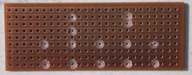
For just one First Step on a 26T34H board


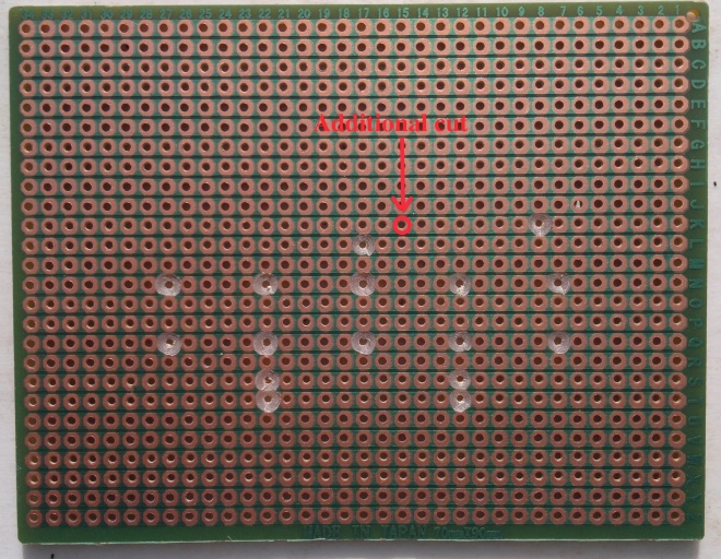
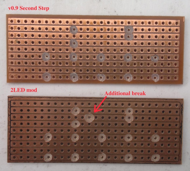
2LED modification
For the 2LED modification,one additional cut is required
Second (and subsequent) Step
As one Second Step Sequencer Bus takes up 9T23H, in order to have four steps, or one bank of four potentiometer stages, on one board, 36T24H board would be needed (the extra hole is a isolating column at the end (9×4+1 = 36). So:
- 95 x 127 mm => 36 strips x 50 holes (1800T), for 2 banks of four stages (with a column of drilled tracks down the middle). No space for mounting holes to be drilled, however. Suggested spacing: two blank holes in from one side (the side with the least wide border), one line of drilled holes down the center (for isolation), and one blank hole at the other side (which has the wider border). Or;
- 100 x 240 mm => 36 strips x 92 holes (3312T) for 3 banks of four stages, plus space (10 holes either side) for mounting holes (The board is almost wide enough for four banks of four, but it is four holes short);
- 100 x 250 mm => 35 strips x 96 holes (3360T) almost 4 banks of four stages but one track short;
- 95 x 432 mm => 36 strips x 170 holes (6120T) for 7 banks of four stages (with one hole spare either side – not enough for mounting holes to be drilled).
For one bank of eight potentiometer stages on one board, 62T24H board would be needed:
- 180 x 300 mm => 63 strips x 108 holes for four banks of eight stages, plus space for mounting holes (6 holes wide each side)
Gallery of cuts
Template for one Second step
On a 36T50H, 2 banks of four Second Steps


The two templates side by side:


Note that it could be possible to omit the center cut on the GND lines (line(s) 2 and 3 – (second and) third up from the bottom). Line 3 is the principle GND line – however, the adjacent line 2 can also be used, by using double row header pins (across tracks 2 and 3) are soldering the two lines together. Omitting these cuts would result it less link wires required. See this example of a partially drilled veroboard and note the vertical center line, with the omitted drilled out hole pairs:
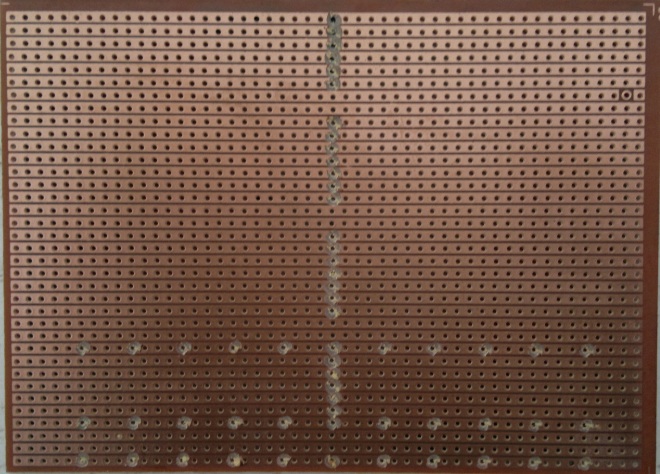
In fact, it is possible to use the spare one or two holes on the left or right sides respectively, to hard link the GND lines, of the disparate sequencer bus steps, using just three soldered link wires. Note the line of black GND links on the right hand side of the board:

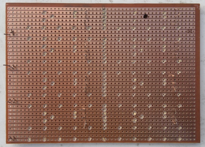
Here is the completed underside. Note the erroneous position of one cut (for the 2LED mod) on the top right hand bank. This doesn’t actually affect operation or require component replacement nor rework:
2LED modification
Economics
First step
To be calculated…
Second step
Given that 9T24H is 1.09 for 5, or £0.22 each
36T50 is £3.15 for 5 or £0.63each. Compared with eight 9T24H boards costing at total of £1.76, it is about 35% of the cost
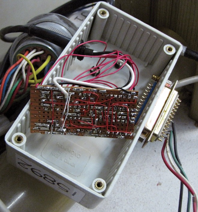
Case and mounting
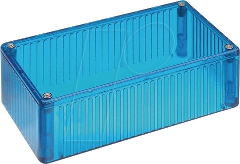
From THE LOST ART OF STRIP BOARD PROTOTYPING, this is the sort of enclosure that I need:
It has internal “ribbing” for slotting the board(s) into and appears to be called a project box. Also this pretty one (original image)
Suppliers:
100x50x25
- 1591ATCL – Plastic Enclosure, Multipurpose, Polycarbonate, 25 mm, 50 mm, 100 mm, IP54, £4.30
- 1591ATRD – Plastic Enclosure, Multipurpose, Polycarbonate, 25 mm, 50 mm, 100 mm, IP54, £3.26
- 1591ATBU – Plastic Enclosure, Multipurpose, Polycarbonate, 100 mm, 50 mm, 25 mm, IP54, £3.06
But these dimensions will not fit stripboards of the following dimensions (as they are either too narrow for 25 x 64 mm or too shallow for 65 x 95 mm boards)
- 25 x 64 mm => 9 strips x 24 holes (225T), nor
- 65 x 95 mm (2.5″ x 3.75″) => 24 strips x 37 holes (888T)
Likewise for all of these:
80x40x20
80x40x15
80x40x20
DIY Enclosure
Here is a box, made from veroboard (page liable to crash):
- DIY Modular Stripboard / Perfboard Casing for Raspberry Pi (Part 1)
- DIY Stripboard/Veroboard Enclosure for Raspberry Pi (Part 2)

Video: DIY Modular Stripboard / Perfboard Enclosure for Raspberry Pi
